The VCCp pin of the TMS320F240 slave DSP selects the protection
mode of the flash memory and the slave DSP watchdog mode:
n If the jumper connects VCCp to VCC (default setting):
n erase/write operations to the flash memory are enabled
n the watchdog is disabled
n If the jumper connects VCCp to GND:
n erase/write operations to the flash memory are disabled
n the watchdog is enabled
The dSPACE software does not support the watchdog of
the slave DSP. For this reason, do not change the jumper’s
default setting shown above.
Jumper settings
Status LEDs of the DS1103
The DS1103 is equipped with 4 red status LEDs that provide
information on the current board status.
Objective
For details on the location of the status LEDs, see the illustration in
Board Overview on page 105.
LED location
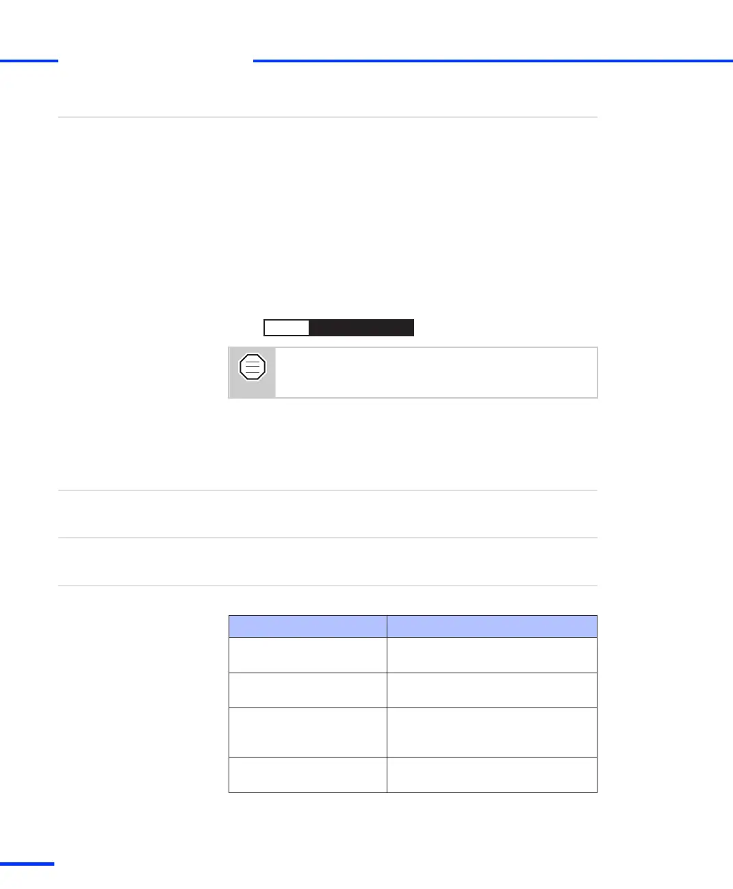
The following table provides a description of the LEDs:
LED Description
PGVCC1
(built‑in up to DS1103-07)
Lit when power is supplied correctly
to the processor core.
PGVCC2
(built‑in up to DS1103-07)
Lit when power is supplied correctly
to the digital logic of the DS1103.
PWR
(built‑in as of DS1103-09)
Lit when power is supplied correctly
to the processor core and the digital
logic of the DS1103.
ENIO
(built‑in as of DS1103-09)
Lit when the I/O functions of the
DS1103 are enabled.
LED description
s
Connector Pinouts and LEDs
t
124
s
DS1103 Hardware Installation and Configuration November 2014