Slave I/O
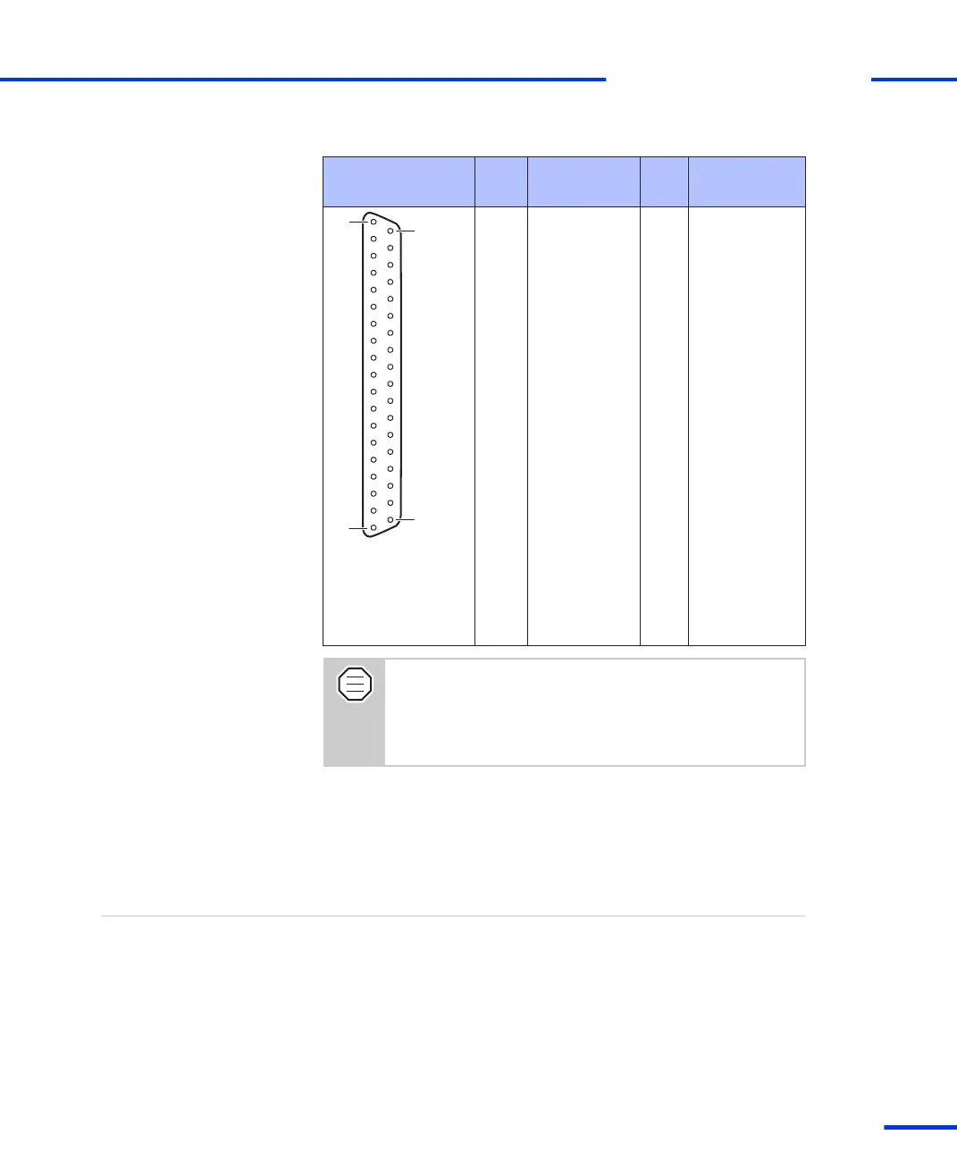
Connector (CP31)
Pin Signal Pin Signal
1 GND
2 SCAP1 20 GND
3 SCAP3 21 SCAP2
4 GND 22 SCAP4
5 ST2PWM 23 ST1PWM
6 GND 24 ST3PWM
7 SPWM1 25 GND
8 SPWM3 26 SPWM2
9 SPWM5 27 SPWM4
10 SPWM7 28 SPWM6
11 SPWM9 29 SPWM8
12 STMRCLK 30 GND
13 GND 31 STMRDIR
14 STINT1 32 SPDPINT
15 GND 33 STINT2
16 SSIMO 34 SSOMI
17 SCLK 35 SSTE
18 SXF 36 SBIO
19 VCC (+5 V) 37 GND
The VCC1, VCC2 and VCC3 line of the DS1103 are
connected on the CP1103/CLP1103 and called VCC. The
total load of all connector pins that provide access to the
PC power supply must not exceed 1.5 A (CP1103) or 0.75
A (CLP1103).
Incremental Encoder Interface Connectors (CP32 ... CP37,
CP39)
The incremental encoder interface connectors (CP32 ... CP37 and
CP39) are 15-pin, female Sub-D connectors located on the front of
the connector panel. Each of the connectors provides the signals for
one of the seven available incremental encoder channels.
Objective
s
CP1103/CLP1103 Components
t
DS1103 Hardware Installation and Configuration November 2014
133
t