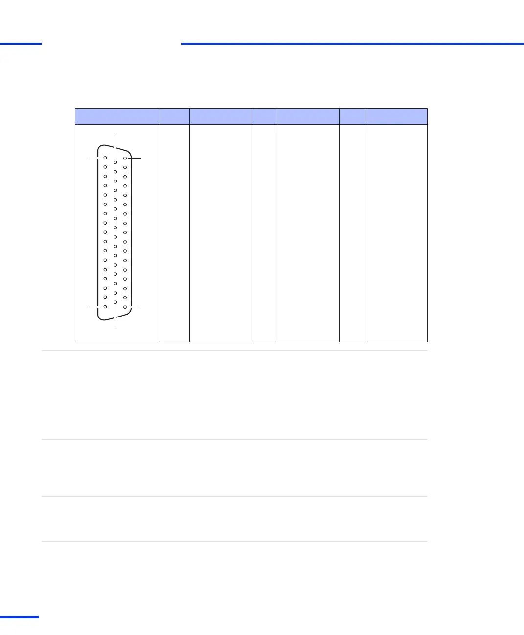
The table below shows the pin assignment of the Sub-D connector
P1B.
Connector P1B Pin Signal Pin Signal Pin Signal
1 GND 34 ADCH1
2 ADCH3 18 GND 35 GND
3 GND 19 ADCH5 36 ADCH7
4 ADCH9 20 GND 37 GND
5 GND 21 ADCH11 38 ADCH13
6 ADCH15 22 GND 39 GND
7 GND 23 ADCH17 40 ADCH19
8 GND 24 GND 41 GND
9 GND 25 DACH1 42 DACH3
10 DACH5 26 GND 43 GND
11 GND 27 DACH7 44 GND
12 SADCH1 28 GND 45 GND
13 GND 29 SADCH3 46 SADCH5
14 SADCH7 30 GND 47 GND
15 GND 31 SADCH9 48 SADCH11
16 SADCH13 32 GND 49 GND
17 GND 33 SADCH15 50 SADCSOC
References
• Board Overview on page 105
Related topics
Digital Connector (P2)
The digital connector (P2) is a 100‑pin, high density KEL connector. It
is used to obtain access to the digital signals of the board. The
connector is located on the bracket of the DS1103, see Board
Overview on page 105.
Purpose
Using the adapter cable supplied with the board, the digital
connector (P2) can be linked to two 50-pin, female Sub‑D connectors
(labeled P2A, P2B).
Adapter cable
For detailed information (I/O circuits, electrical characteristics, etc.) on
the I/O lines terminating at the I/O connector, see Signal Connection
to External Devices on page 161.
Signal specification
s
Connector Pinouts and LEDs
t
112
s
DS1103 Hardware Installation and Configuration November 2014