Information in this section
DS814 Board Overview 229
DS814 Data Sheet 230
DS814 Board Overview
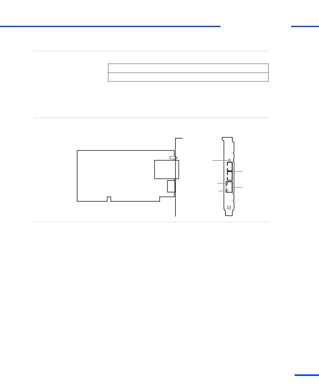
The illustration shows the location of connectors and LEDs on the
board. The illustration is not to scale.
Overview illustration
Fiber optic
connectors
Patch cable
connector
Red
Green
Yellow
Status LEDs:
RX
TX
The DS814 contains the following board elements:
n Status LEDs display the current status of the connection. These
LEDs can be used for troubleshooting purposes:
n A lit yellow LEDindicates that the connection between the box
and the host PC (or DS830) is ready for communication.
n A lit red LED indicates that the active connection between the
box and the host PC (or DS830) uses a fiber‑optic cable.
n A lit green LED indicates that data is being sent or received.
n Fiber optic connectors are used for the optical link to the link
board installed in the host PC or to a DS830 Multilink Panel. The
DS814 provides one receiver port (RX) and one transmitter port
(TX).
n Patch cable connector is an RJ45 connector. It is used for the link
via crossed‑over patch cable to the link board installed in the host
PC or to a DS830 Multilink Panel.
Components
Where to go from here
s
Link Boards and Panels
t
DS1103 Hardware Installation and Configuration November 2014
229
t