An adapter cable is available for the new DS815 connector to adapt
the DS815 to a standard patch cable with an RJ45 connector. The
adapter cable is labeled “DS815-RJ45 Vs 2.0”.
For the connection between the DS815-RJ45 adapter cable
and the DS814 Link Board (Box), you must use a
crossed‑over patch cable.
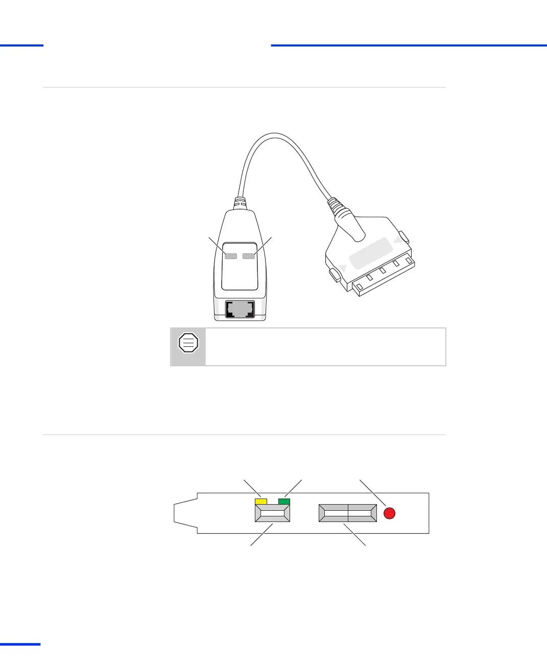
DS815-RJ45 adapter cable
Identifying the Connection Status
Three LEDs on the brackets of the DS814, DS817 and DS819 indicate
the current status of the connection.
Yellow Green Red
Patch cable connector Fiber-optic connector
Yellow LED A lit yellow LED indicates that the connection between
the host PC and the expansion box is ready for communication.
DS814, DS817, DS819
s
Connecting an Expansion Box to the Host PC
t
62
s
DS1103 Hardware Installation and Configuration November 2014