The input signals pass through a differential amplifier before the
resulting difference is passed to further internal circuits.
The reference voltage U_REF/2 is used for centering the signals.
The analog encoder interface (Ch7) has the following input
characteristics.
Parameter Value
1 V
pp
differential
mode
Peak‑to‑peak input voltage n Min. 0.8 V
pp
n Max. 1.2 V
pp
Input impedance 120 Ω
Voltage range for external
mean voltage (V
CM
)
0 … 2.5 V
11 μA
pp
differential
mode
Peak‑to‑peak input current n Min. 7 μA
pp
n Max. 16 μA
pp
Input impedance 200 Ω
Power-up default The behavior of inputs is
not critical for
connected devices.
Electrical characteristics
References
• Encoder providing single
‑
ended 1 V
pp
signals on page 184
Related topics
Recognizing Encoder Index Interrupts
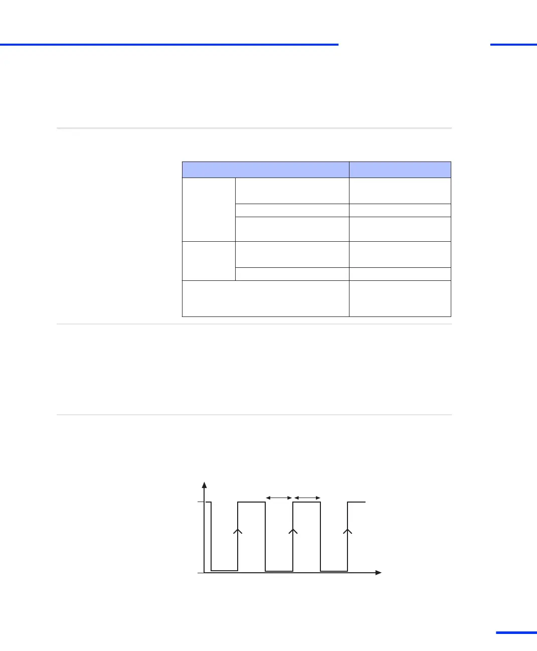
To allow the interrupt controller to recognize incoming index
interrupts (IDX1 … IDX7), the input of the index interrupts must be
kept low for at least 100 ns. The interrupt is activated by the low to
high transition of the signal. The signal must remain high for at least
100 ns after the transition from low to high.
high
low
t
T
high
T
low
T
high min
: 100 ns
T
low min
:
100 ns
Request for recognizing
s
Incremental Encoder Interface
t
DS1103 Hardware Installation and Configuration November 2014
181
t