Digital I/O Connector
(CP30)
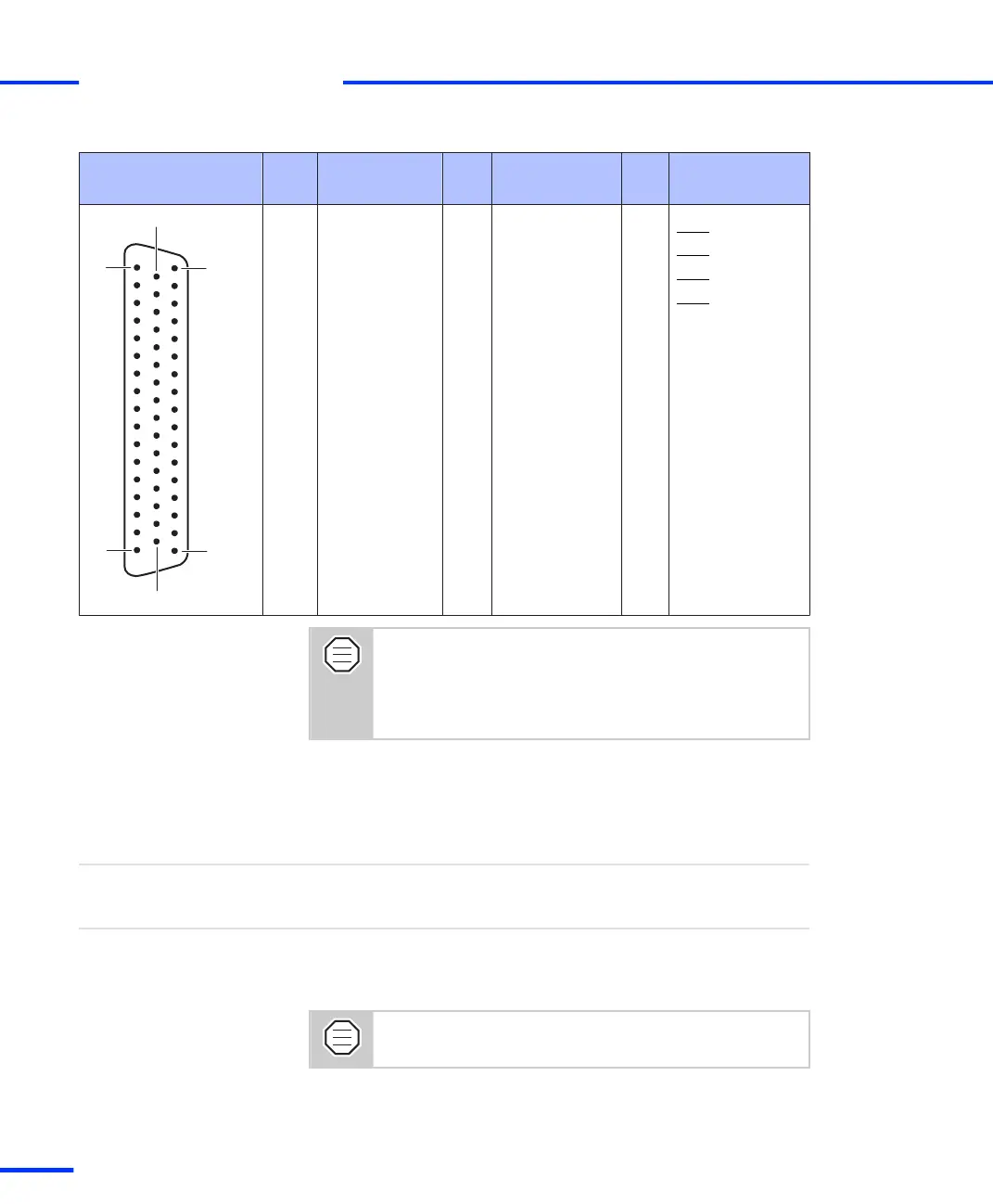
Pin Signal Pin Signal Pin Signal
17 GND 50 VCC (+5 V)
16 IO30 33 IO31 49 INT3
15 IO28 32 IO29 48 INT2
14 IO26 31 IO27 47 INT1
13 IO24 30 IO25 46 INT0
12 IO22 29 IO23 45 GND
11 IO20 28 IO21 44 GND
10 IO18 27 IO19 43 GND
9 IO16 26 IO17 42 GND
8 IO14 25 IO15 41 GND
7 IO12 24 IO13 40 GND
6 IO10 23 IO11 39 GND
5 IO8 22 IO9 38 GND
4 IO6 21 IO7 37 GND
3 IO4 20 IO5 36 GND
2 IO2 19 IO3 35 GND
1 IO0 18 IO1 34 GND
The VCC1, VCC2 and VCC3 line of the DS1103 are
connected on the CP1103/CLP1103 and called VCC. The
total load of all connector pins that provide access to the
PC power supply must not exceed 1.5 A (CP1103) or 0.75
A (CLP1103).
Slave I/O Connector (CP31)
The slave I/O connector (CP31) is a 37-pin, female Sub-D connector
located on the front of the connector panel.
Objective
Because the pin numbering used for Sub-D connectors is not
standardized, the following figure shows the numbering scheme used
(front view).
Do not rely on the numbers written on Sub-D
connectors.
Pinout
s
Connector Pinouts and LEDs
t
132
s
DS1103 Hardware Installation and Configuration November 2014