The table below shows the pin assignment of the Sub-D connector
P2B.
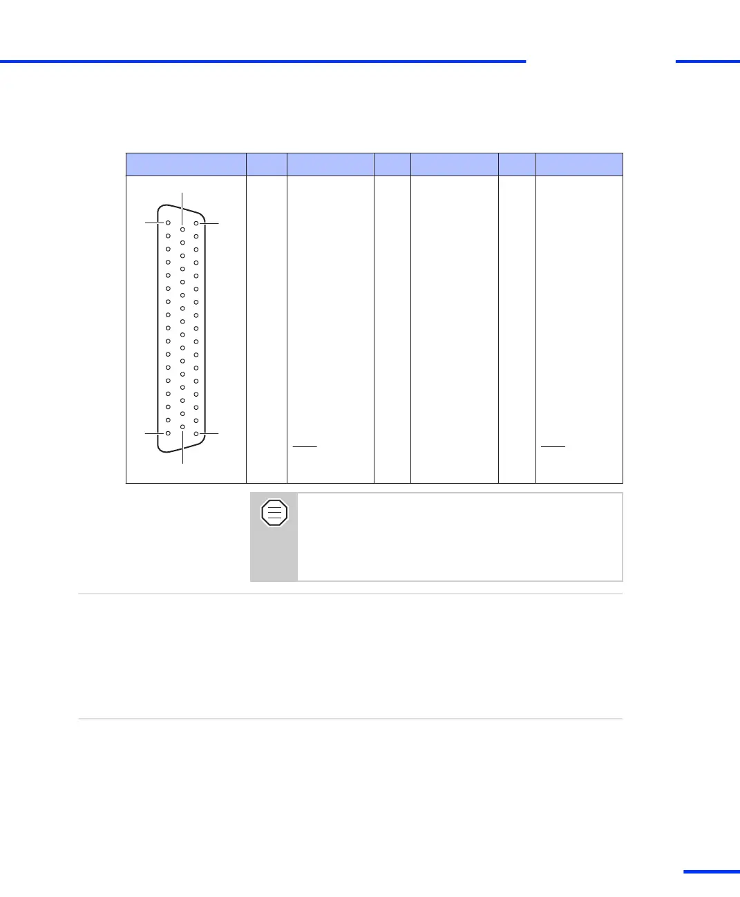
Connector P2B Pin Signal Pin Signal Pin Signal
1 GND 34 GND
2 IO2 18 IO0 35 GND
3 IO6 19 IO4 36 GND
4 IO10 20 IO8 37 GND
5 IO14 21 IO12 38 GND
6 IO18 22 IO16 39 GND
7 IO22 23 IO20 40 GND
8 IO26 24 IO24 41 GND
9 IO30 25 IO28 42 GND
10 STMRDIR 26 STINT1 43 GND
11 ST3PWM 27 ST1PWM 44 GND
12 SPWM3 28 SPWM1 45 SPWM5
13 SPWM9 29 SPWM7 46 GND
14 SCAP3 30 SCAP1 47 GND
15 SSCLK 31 SXF 48 SSIMO
16 INT0 32 GND 49 INT2
17 VCC1 (+ 5 V) 33 VCC1 (+ 5 V) 50 GND
The DS1103 provides three VCC lines. The total load of
every VCC line (VCC1, VCC2, VCC3) must not exceed 500
mA.
For details on the VCC lines refer to Power Supply Outputs
on page 162.
References
• Signal Connection to External Devices on page 161
Related topics
Incremental Encoder/Digital Connector (P3)
The incremental encoder/digital connector (P3) is a 100‑pin, high
density KEL connector. It is used to obtain access to the signals of the
incremental encoder channels. The connector is located on the
bracket of the DS1103, see Board Overview on page 105.
Purpose
s
DS1103 Components
t
DS1103 Hardware Installation and Configuration November 2014
117
t