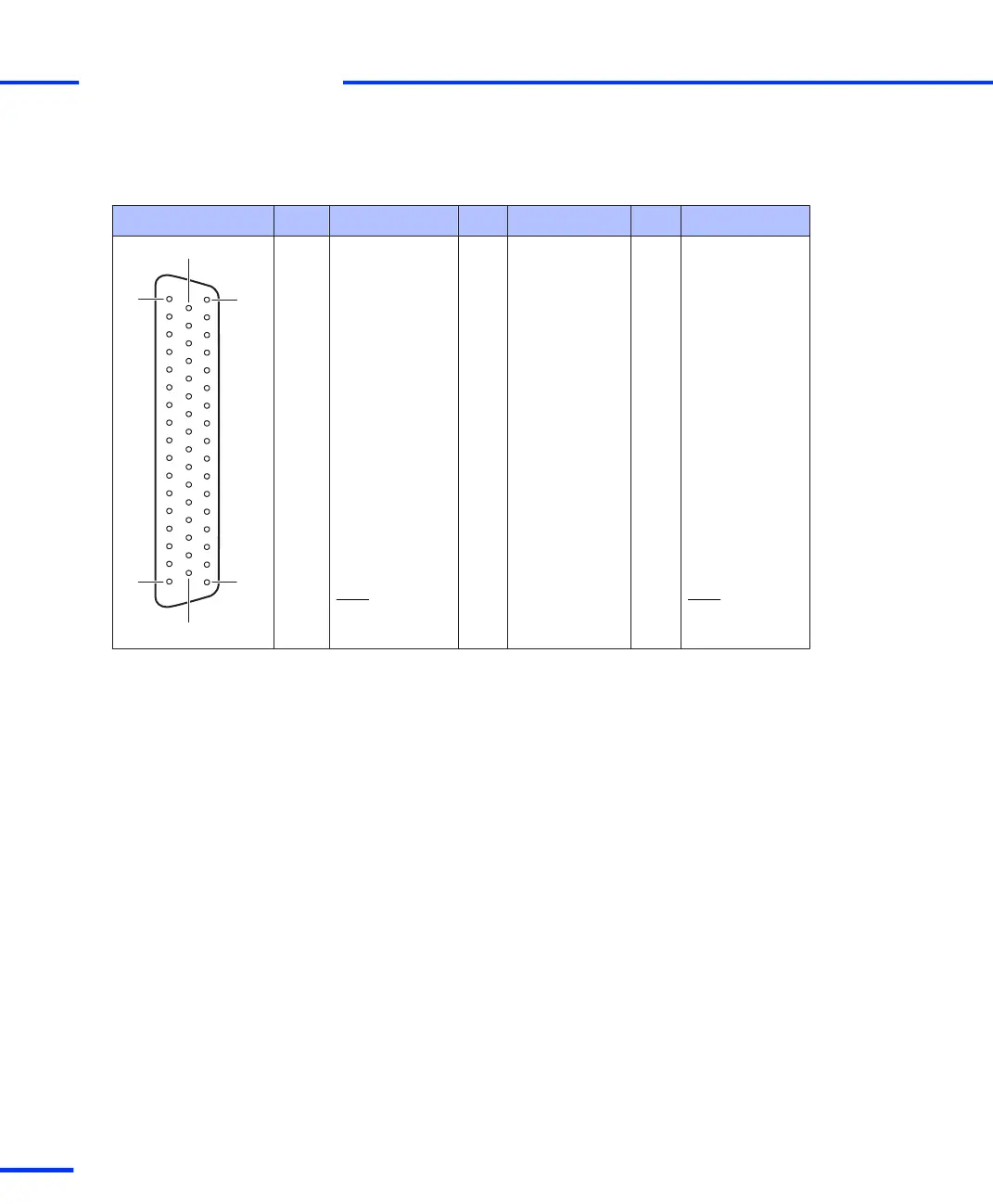
The table below shows the pin assignment of the Sub-D connector
P2A.
Connector P2A Pin Signal Pin Signal Pin Signal
1 GND 34 GND
2 IO3 18 IO1 35 GND
3 IO7 19 IO5 36 GND
4 IO11 20 IO9 37 GND
5 IO15 21 IO13 38 GND
6 IO19 22 IO17 39 GND
7 IO23 23 IO21 40 GND
8 IO27 24 IO25 41 GND
9 IO31 25 IO29 42 GND
10 STMRCLK 26 STINT2 43 GND
11 SPDPINT 27 ST2PWM 44 GND
12 SPWM4 28 SPWM2 45 SPWM6
13 GND 29 SPWM8 46 GND
14 SCAP4 30 SCAP2 47 GND
15 SSTE 31 SBIO 48 SSOMI
16 INT1 32 GND 49 INT3
17 VCC1 (+ 5 V) 33 VCC1 (+ 5 V) 50 GND
s
Connector Pinouts and LEDs
t
116
s
DS1103 Hardware Installation and Configuration November 2014