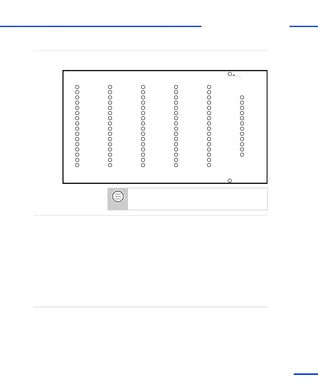
In the illustration below you will find the signal names as labeled on
the panel template.
LED assignment
Holes for
(not to scale)
19" rack mount
IO0
IO1
IO2
IO3
IO4
IO5
IO6
IO7
IO8
IO9
IO10
IO11
IO12
IO13
IO14
IO15
IO16
IO17
IO18
IO19
IO20
IO21
IO22
IO23
IO24
IO25
IO26
IO27
IO28
IO29
IO30
IO31
SPWM1
SPWM2
SPWM3
SPWM4
SPWM5
SPWM6
SPWM7
SPWM8
SPWM9
ST1PWM
ST2PWM
ST3PWM
SCAP1
SCAP2
SCAP3
SCAP4
INT0
INT1
INT2
INT3
STINT1
STINT2
SPDPINT
STMRCLK
STMRDIR
SXF
SBIO
SSTE
SCLK
SSIMO
SSOMI
CAN
TXD
RXD
DCD (/RXD)
RTS
DTR (/RTS)
CTS
DSR (/CTS)
RI
STXD
SRXD
Phi0 1
Phi90 1
Index 1
Phi0 2
Phi90 2
Index 2
Phi0 3
Phi90 3
Index 3
Phi0 4
Phi90 4
Index 4
Phi0 5
Phi90 5
Index 5
Phi0 6
Phi90 6
Index 6
The LEDs display the TTL signal level, not the active status
of the signal. (TTL “high” → LED is on; TTL “low” → LED is
off).
In order to keep the loading of the signals as low as possible, the
LEDs are run through buffers.
For the incremental sensor signals, there are buffers with true
differential inputs. The pulse length of data signals (CAN, RXD, TXD,
SRXD, STXD) is extended to make even small blocks of data visible.
The power required by the LEDs is taken from the DS1103’s supply
voltage (VCC).
Electrical characteristics
BNC Connectors (CP1 ... CP28)
The CP1 ... CP28 connectors are female BNC connectors. Their shells
are connected to GND.
Objective
s
CP1103/CLP1103 Components
t
DS1103 Hardware Installation and Configuration November 2014
129
t