The DS821 contains the following element:
n Status LEDs display the current status of the connection. These
LEDs can be used for troubleshooting purposes:
n A lit yellow LED indicates that the connection between the host
PC and a dSPACE box (or DS830) is ready for communication.
n A lit green LED indicates that data is being sent or received.
n Patch cable connector is an RJ45 connector. It is used for the link
via crossed‑over patch cable to the DS814 Link Board (Box), DS830
or MicroAutoBox.
DS821 components
DS821 Data Sheet
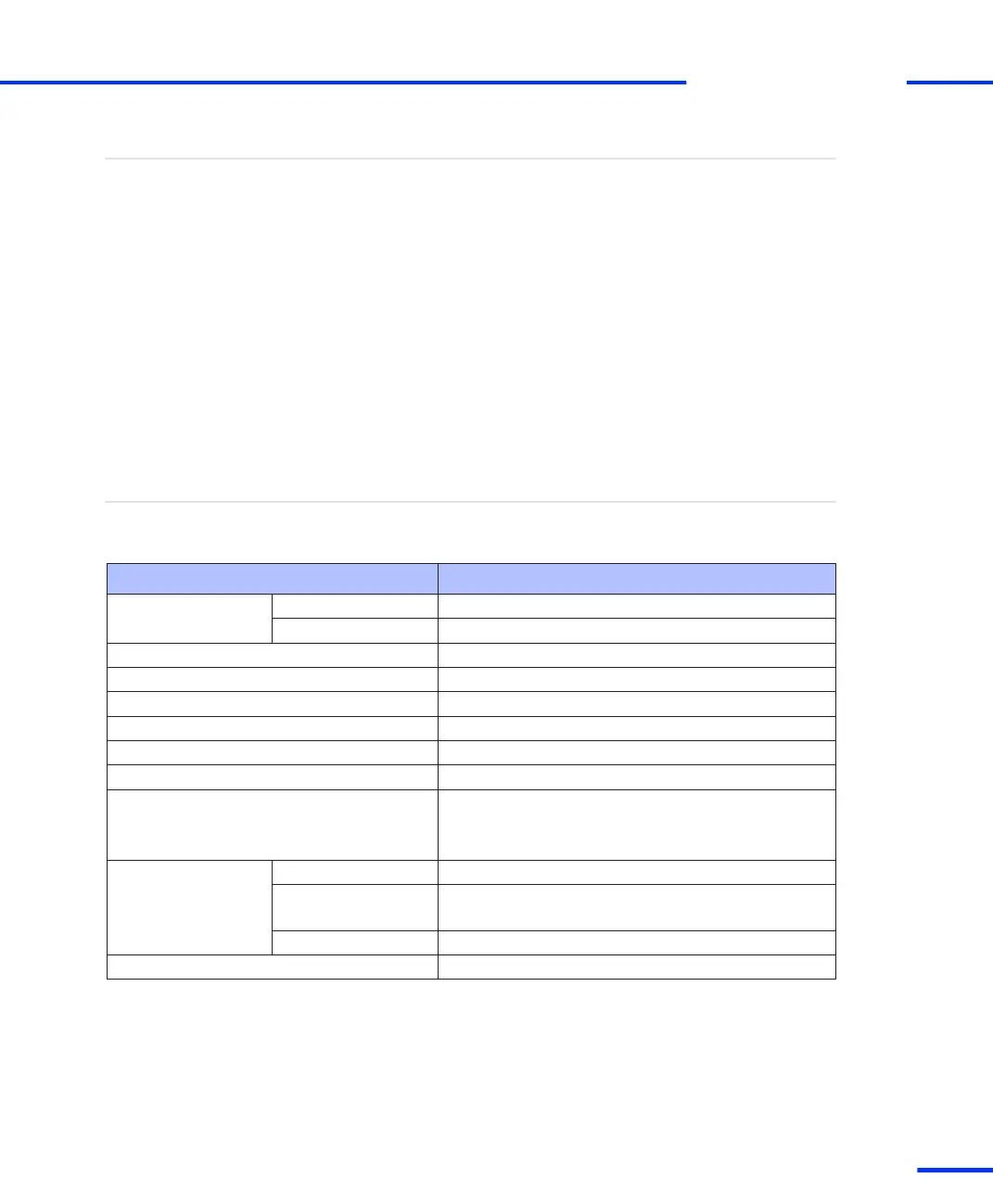
The following table provides the technical characteristics of the
DS821 Link Board (PC):
Technical data
Parameter Specification
Host interface DS821‑34 mm ExpressCard/34
DS821‑54 mm ExpressCard/54
Required software dSPACE Release 5.2 or later
Supported link interfaces DS814, DS830, MicroAutoBox
Physical connection Crossed‑over patch cable: twisted pair (CAT5 STP)
Cable length per connection Max. 10 m
Protocol High‑speed serial link (proprietary)
Max. transfer rate 100 MBit/s
1)
Power supply From PC:
n +3.3 V ±5%, 1.0 A
n +1.5 V ±5%, 0.5 A
Physical size DS821‑34 mm 112 x 34 x 12 mm (4.4 x 1.3 x 0.5 in.)
DS821‑34 mm (Ver.
2.0)
112 x 34 x 21,5 mm (4.4 x 1.3 x 0.85 in.)
DS821‑54 mm 120 x 54 x 22 mm (4.7 x 2.1 x 0.9 in.)
Ambient temperature 0 … 70 ºC (32 … 158 ºF)
1)
The transfer rate describes the capabilities of the hardware components and circuits of dSPACE products. Depending on the
software complexity the attainable overall performance can deviate significantly from the hardware specification.
s
Link Boards and Panels
t
DS1103 Hardware Installation and Configuration November 2014
241
t