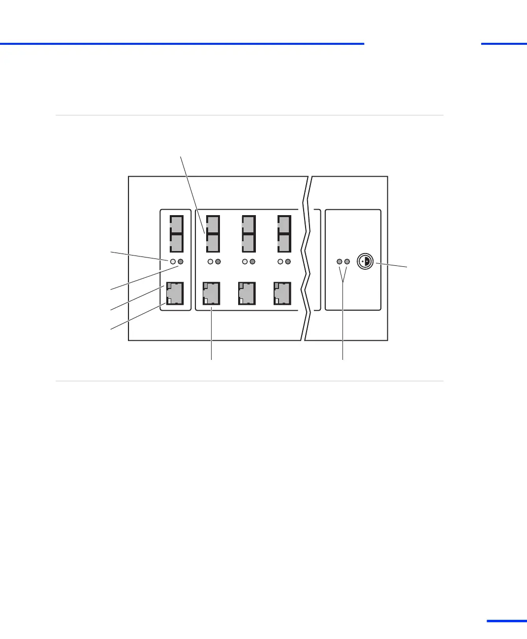
DS830 Panel Overview
The illustration shows the location of connectors and LEDs on the
panel. The illustration is not to scale.
Overview illustration
Green
Red
Fiber-optic connector
Patch cable connector
Power
connector
PC Box1 Box2 Box3
Power LEDs
Power
Connection
status LEDs:
Yellow
(fiber-optic
connector)
Yellow
(patch cable
connector)
TX
RX
The DS830 contains the following elements (from left to right):
n Connection status LEDs display the current status of the
connection. These LEDs can be used for troubleshooting purposes:
n A lit yellow LED (fiber‑optic connector) indicates that the
connection between host PC and the corresponding dSPACE
box is currently being used for communication.
n A lit yellow LED (patch cable connector) indicates that the
connection to the host PC or a connected dSPACE box is ready
for communication.
n A lit red LED indicates that the corresponding connection to
the host PC or a connected dSPACE box uses a fiber‑optic
cable.
n A lit green LED indicates that data is being sent or received on
the corresponding connection.
Components
s
Link Boards and Panels
t
DS1103 Hardware Installation and Configuration November 2014
243
t