DS819 Board Overview
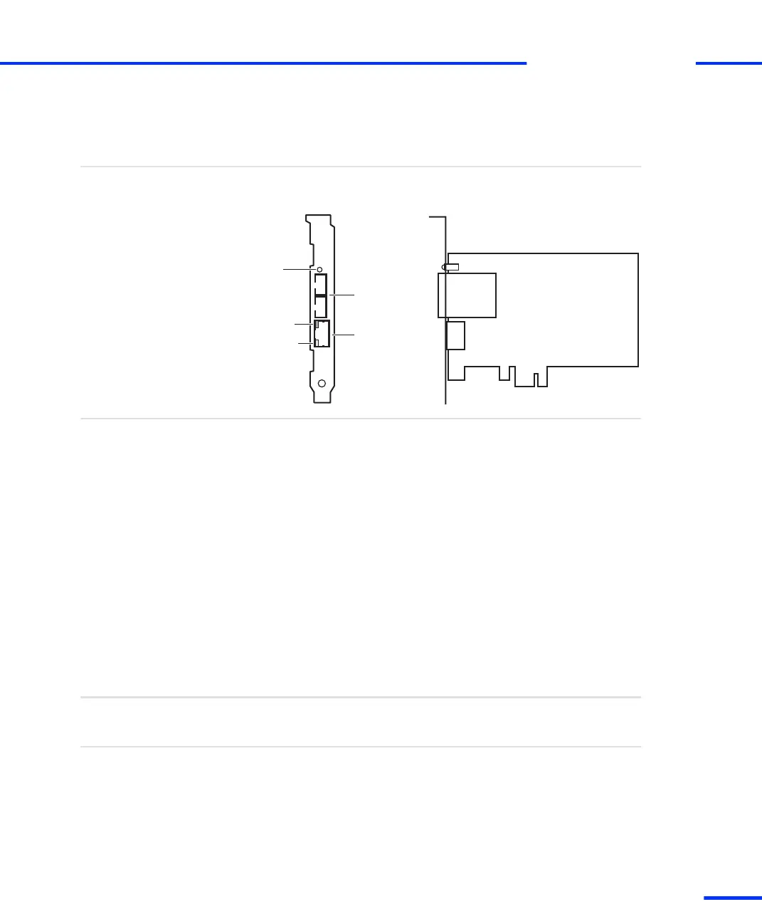
The illustration shows the location of connectors and LEDs on the
board. The illustration is not to scale.
Overview illustration
Fiber optic
connectors
Patch cable
connector
Red
Green
Yellow
Status LEDs:
RX
TX
The DS819 contains the following board elements:
n Status LEDs display the current status of the connection. These
LEDs can be used for troubleshooting purposes:
n A lit yellow LED indicates that the connection between the host
PC and a dSPACE box (or DS830) is ready for communication.
n A lit red LED indicates that the active connection between the
host PC and a dSPACE box (or DS830) uses a fiber‑optic cable.
n A lit green LED indicates that data is being sent or received.
n Fiber optic connectors are used for the optical link to the DS814
Link Board (Box) or DS830. The DS819 provides one receiver port
(RX) and one transmitter port (TX).
n Patch cable connector is an RJ45 connector. It is used for the link
via crossed‑over patch cable to the DS814 Link Board (Box), DS830
or MicroAutoBox.
Components
Matching link cables (fiber optic or crossed-over patch cable) are
delivered with the hardware package. Use only these cables.
Link cables
The DS819 comes with an optional bracket for installation in low-
profile PCs.
Optional bracket
s
Link Boards and Panels
t
DS1103 Hardware Installation and Configuration November 2014
237
t