For single‑ended 1 V
pp
signals, the connection depends on the value
of the mean voltage (V
CM
) of the corresponding signals:
n If the mean voltage of the encoder signals is 0 V, you can connect
pins PHI0, PHI90 and IDX to the GND pin (see example 1 below).
n If the mean voltage is not 0 V (0 V < V
CM
< 2.5 V), you have to
provide this voltage in the range 0 … 2.5 V yourself (see example
2 below).
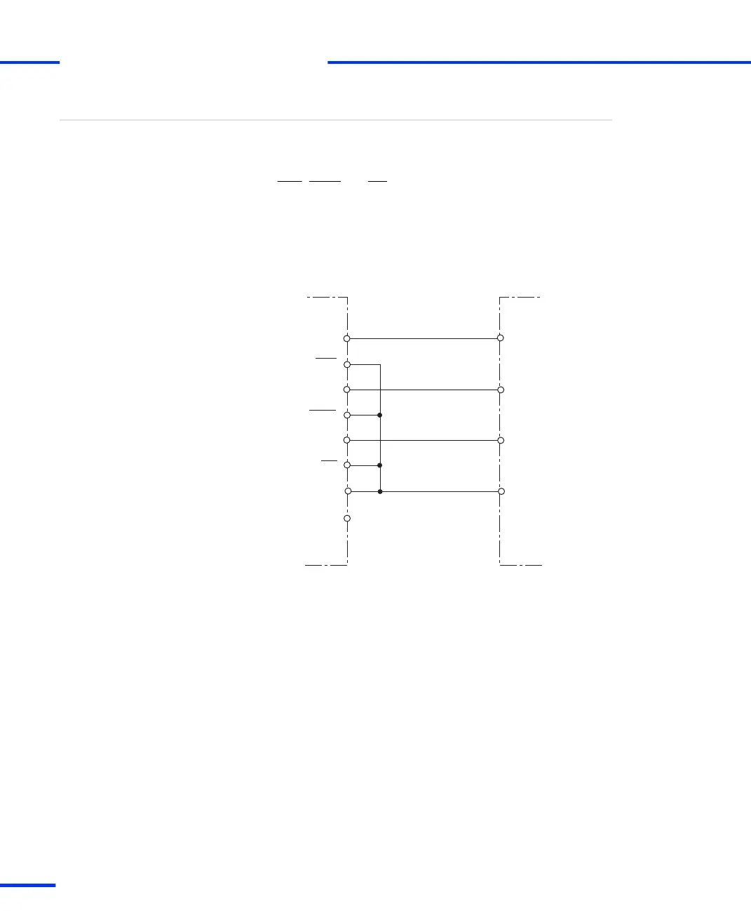
Encoder providing
single‑ended 1 V
pp
signals
Incremental encoderDS1103
PHI0
INDEX
PHI90
GND
Example 1:
V
CM
= 0 V
VCC
GND
PHI0
PHI90
IDX
PHI0
PHI90
IDX
s
Signal Connection to External Devices
t
184
s
DS1103 Hardware Installation and Configuration November 2014