The input circuit depends on the selected signal type.
1 V
pp
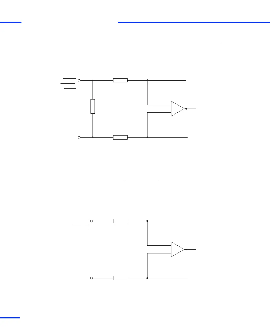
differential mode The following illustration shows a
simplified diagram of the input channel circuitry when you select 1
V
pp
differential mode for analog encoders.
Input circuit
+
–
43 kΩ
120 Ω
43 kΩ
To internal
circuits
PHI0 (7)
PHI90 (7)
IDX (7)
U_REF/2
U_REF/2 = 2.5 V
PHI0 (7)
PHI90 (7)
IDX (7)
The input signals pass through a differential amplifier before the
resulting difference is passed to further internal circuits.
The reference voltage U_REF/2 is used for centering the signals.
It is possible to provide single-ended 1 V
pp
signals. For details on
connecting the PHI0, PHI90 and INDEX lines, refer to Encoder
providing single
‑
ended 1 V
pp
signals on page 184.
11 μA
pp
differential mode The following illustration shows a
simplified diagram of the input channel circuitry when you select 11
μA
pp
differential mode for analog encoders.
+
–
100 Ω
100 Ω
To internal
circuits
U_REF/2
U_REF/2 = 2.5 V
PHI0 (7)
PHI90 (7)
IDX (7)
PHI0 (7)
PHI90 (7)
IDX (7)
s
Signal Connection to External Devices
t
180
s
DS1103 Hardware Installation and Configuration November 2014