As of March 2009, the VBAT wire (red) contains a melting fuse. The
red wire has a cross-section of 10 mm², the black wire of 6 mm².
Depending on the AutoBox version, the melting fuse must have the
following characteristics:
n AutoBox up to Version 3.0: 60 A/32 V, time lag
n AutoBox Version 4.0 and later: 25 A/32 V, time lag
The cable for this AutoBox versions is labeled CB402AB.
To avoid damage, do not use a cable with cross-sections less than 6
mm². Note that the cable which is supplied to connect MicroAutoBox
1401/1507 to the power supply provides only 1.5 mm² cross-section
wires.
WA R NI NG
Hazardous voltages
Even a brief disconnection of the battery while the engine
is running results in a load dump of the car generator
producing hazardous voltages of more than 100 V.
n Turn off the engine while connecting or disconnecting
the car battery.
Not valid for AutoBox Version 4.0 and later:
N O T I C E
Reverse polarity destroys the AutoBox power supply
even if the remote control input is turned off.
n Double check the supply voltage polarity of AutoBox.
Warnings
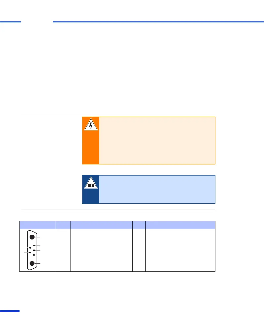
The following illustration shows the pinout (front view).
Pinout
Connector Pin Signal Pin Signal
A2 Positive supply voltage
1)
5 Reserved, do not use
2 Reserved, do not use 4 Remote control
2)
1 Reserved, do not use 3 Reserved, do not use
A1 Negative supply voltage (0 V)
1)
Up to AutoBox Version 3.0: 8 V … 60 V DC. AutoBox Version 4.0 and later: 6 V … 60 V DC.
2)
If you use the matching cable supplied by dSPACE the remote control line is connected to positive supply voltage within the
connector shell. This cable is intended for use with a lab power supply only.
s
Accessories
t
280
s
DS1103 Hardware Installation and Configuration November 2014