CONFIDENTIAL
SHEET
39
NO.
SHEET
REVISION
E
TITLE
NEXT
40
TM-H5000
II
IIII
II
series
Specification
(STANDARD)
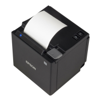
Figure 2.2.5 Drawer Kick-out Drive Signal Output Waveform
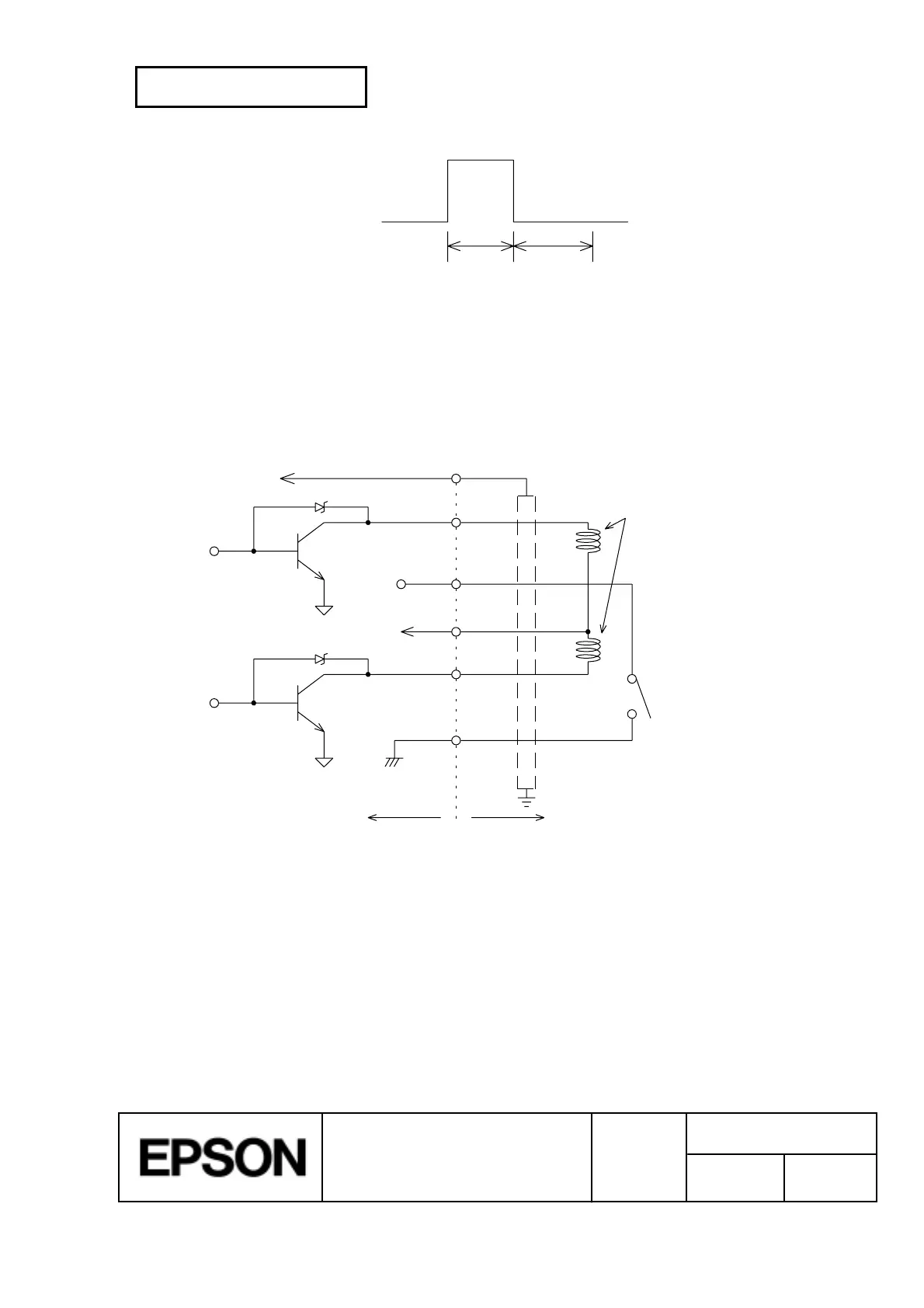
4) Drawer open/close signal
Input signal level (connector pin 3): "L" = 0 to 0.8 V
"H" = 2 to 5 V
Drawer kick-out connector
1
2
3
4
5
6
F. G
P-GND
P-GND
A
B
Printer side User side (Drawer kick-out side)
+24V
With shielded
Drawer kick-out solenoid
Drawer open/close switch
Figure 2.2.6 Drawer Circuitry
NOTES:
1. Two driver transistors cannot be energized simultaneously.
2. The driver must not be energized continuously.
3. Be sure to use the printer power supply (connector pin 4) for the drawer power source.
4. The resistance of the drawer kick-out solenoid must not be less than the specified.
Otherwise, an overcurrent could damage the solenoid.
t 1x 2 msec
t 1x 2 msec
t2x
t2
x 2 msec
t1
x 2 msec

 Loading...