System manual CECX / CPU module
14.8 Configuration
14.8.1 General information
A CECX-system needs data for the configuration of system performance,
its I/O-devices and interfaces. The system reads this data during the start-
up operation and allocates them to its components and devices.
Configuration data is created by included configuration tools.
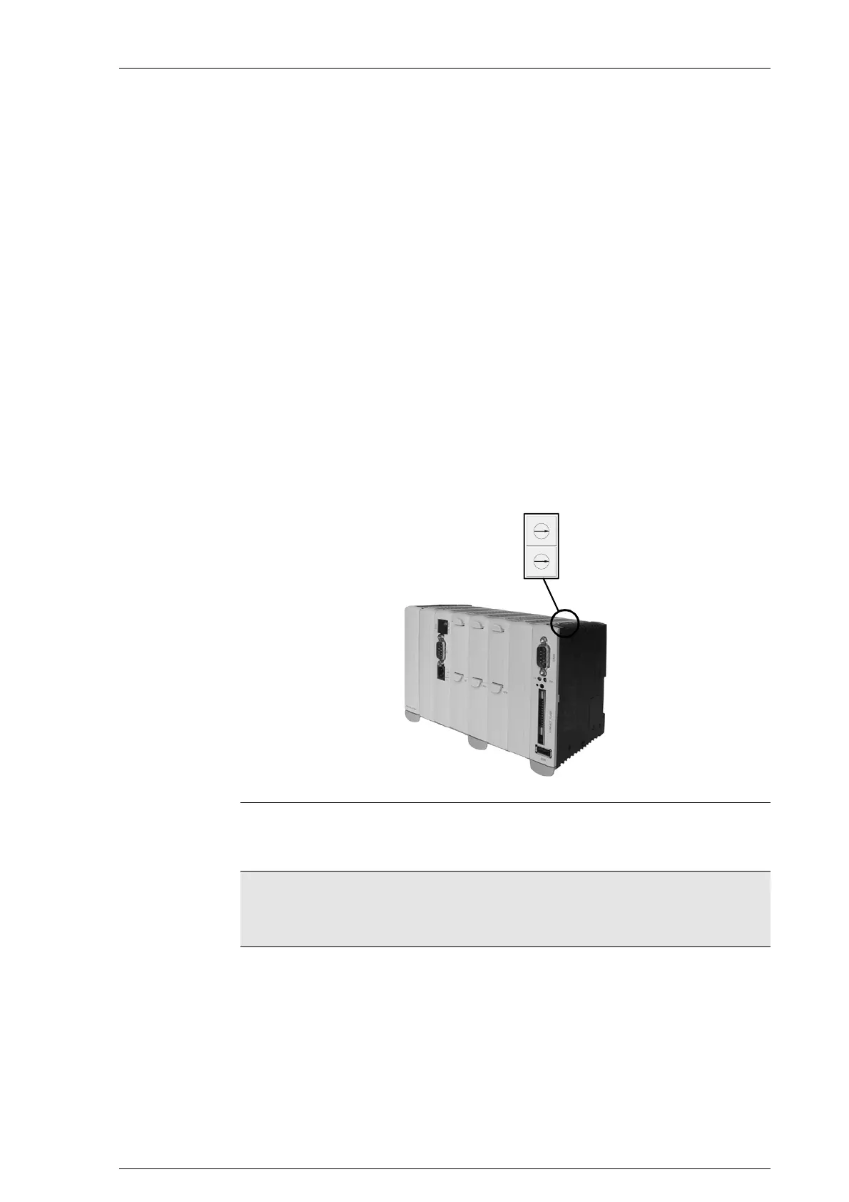
14.8.2 Setting the address
The station address of the CPU module is entered via 2 rotary switches.
(Front address switch: HIGH; back address switch: LOW)
The address switches are located on the top right hand side of casing.
0
1
F
2
3
4
5
6
7
8
9
A
B
C
D
E
0
1
F
2
3
4
5
6
7
8
9
A
B
C
D
E
Position of address switches
On leaving the factory all modules are set to address 0.
Information
Modules of the same type must have different address switch positions
within one CAN bus line. Different modules may have the same address
switch positions.
CECX-II 14-19

 Loading...


