System manual CECX / General assembly and installation instructions
4.3 Footprint
000102030405060708091011121314151617
0V
+24V
NC
NC
NC
NC
NC
NC
NC
NC
DI0
DI1
DI2
DI3
DI4
DI5
DI6
DI7
000102030405060708091011121314151617
0V
+24V
DO0
DO1
DO2
DO3
DI0
DI1
DI2
DI3
+
-
AO0
AO1
AGND
AGND
AI0
+
-
AI1
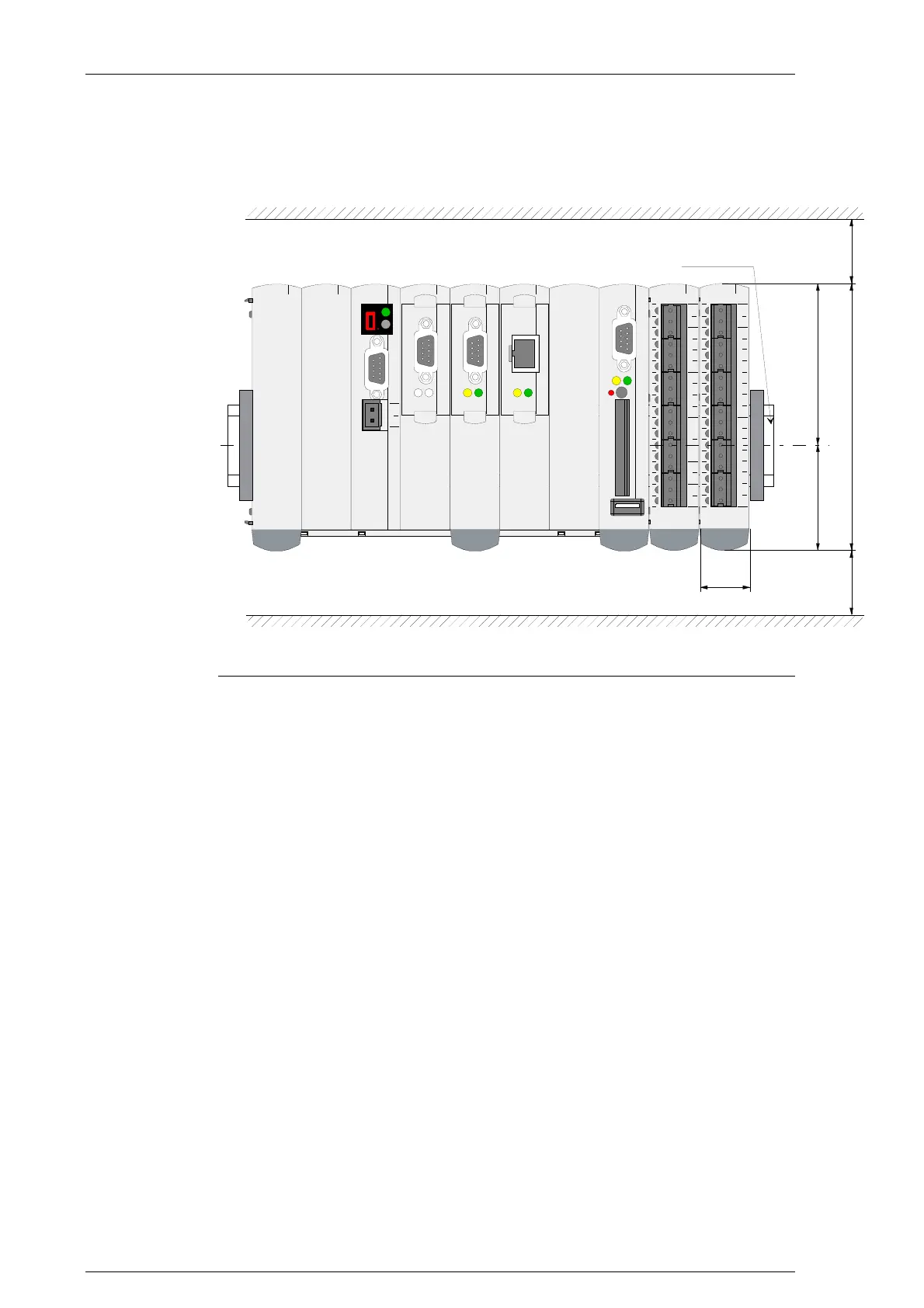
120 3030
50 70
22,5
TS 35x7,5
CAN0
RXTX
Mounting sketch
To ensure air circulation, a free space of at least 30 mm must be main-
tained over and underneath the modules.
4.4 Adding modules
Up to 12 modules (I/O, technology or field bus modules) can be lined up
next to each other in any order on the right side of the CPU module. The
connection between the CPU module and the added modules is estab-
lished via a parallel K-Bus. The entire package is snapped onto a mounting
rail (mounting rail TS 35x7.5).
For the calculation of the number of modules that can be added, the speci-
fied performance value given in the technical specifications under "power
consumption 5 V on the K-Bus" and under "power consumption 24 V on the
K-Bus" must be used. This value must not exceed the value made available
for added modules of the CPU modules or the bus coupling modules.
CECX-II 4-2

 Loading...


