System manual CECX / Ethernet option module CECX-C-ET
CECX-II 33-7
33.5 Connections and wiring
33.5.1 Ethernet interface
33.5.1.1 Pin assignment
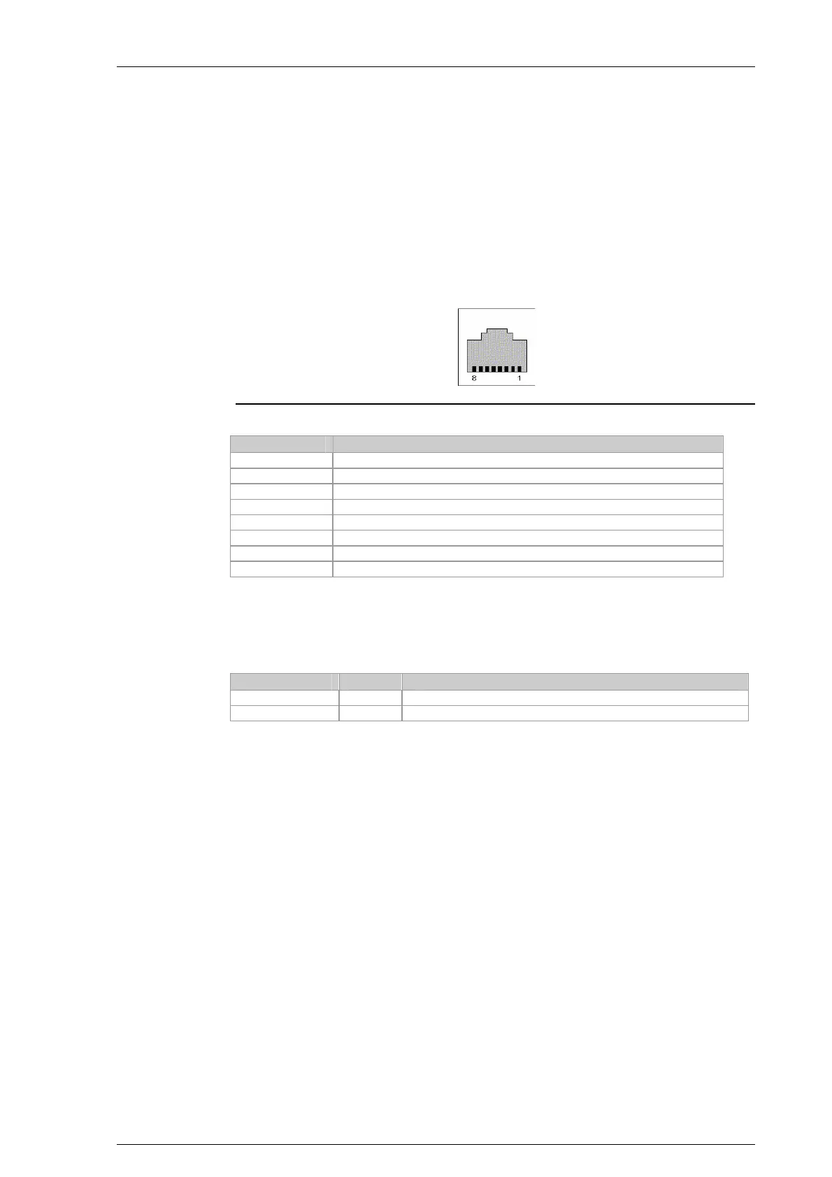
Ethernet connection
PIN-No. Name
01 Transmit data+ (pair 1)
02 Transmit data- (pair 1)
03 Transmit data+ (pair 2)
04 n.c.
05 n.c.
06 Receive data- (pair 2)
07 n.c.
08 n.c.
33.5.1.2 Ethernet status LEDs
2 status LEDs are located below the Ethernet socket (RJ-45):
Name Color Description
Activity LED Yellow Lights up when sending and receiving data.
Link status LED Green Lights up as soon as an Ethernet connection is alive.
33.5.1.3 Cable and plug specification
See chapter "General information about interfaces".
33.5.2 EMC and wiring guidelines
Information: See chapter EC directives and standards.
Pay attention from the outset to careful wiring and shielding.
Further information: See system manual.

 Loading...


