System manual CECX / Serial option module CECX-S-S4
CECX-II 32-10
32.5.2.3 Line terminating board
To activate the bus termination at the last participant during RS-485 opera-
tion the pins 2 and 7 (TERM A, TERM B) must be connected.
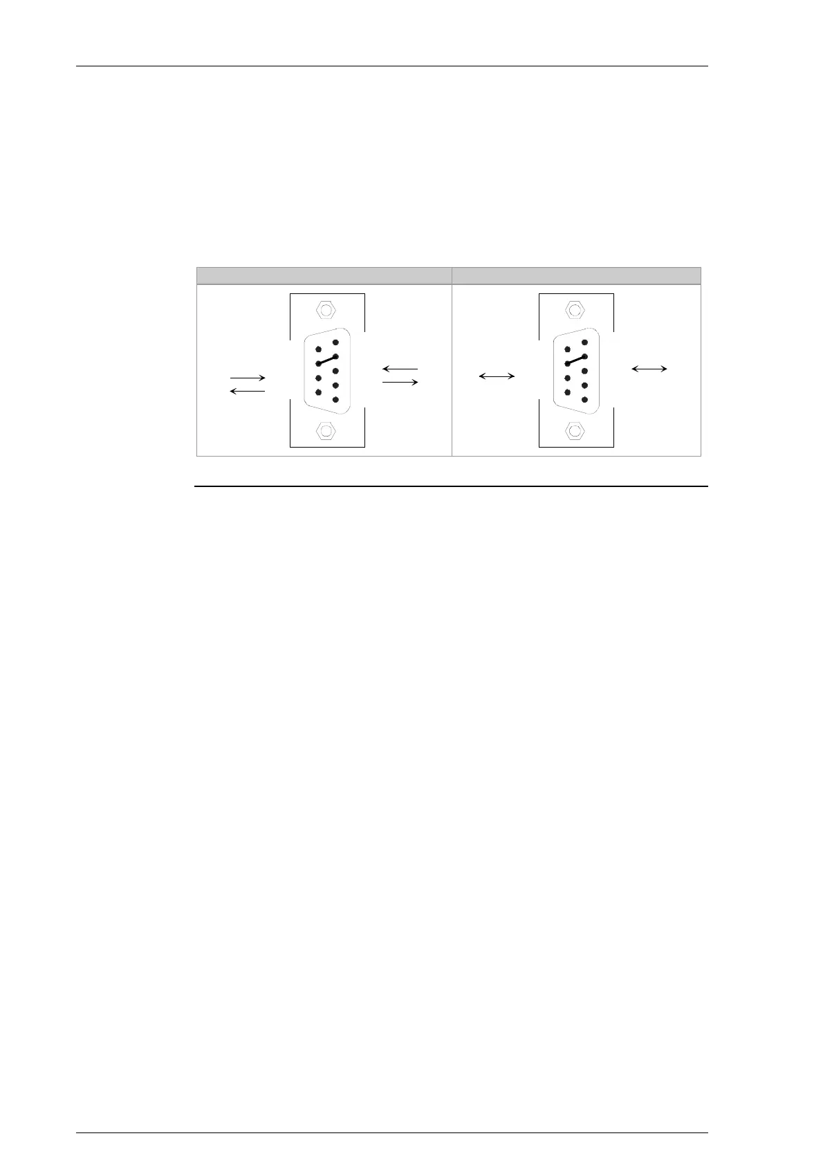
During RS-422-A operation, pins 2 and 7 (TERM A, TERM B) must always
be connected.
RS-422-A RS-485-A
1
5
9
6
n.c.
TERM A
A'
A
GND
TERM B
B'
B
GND
1
5
9
6
n.c.
TERM A
A/A'
do not connect
GND
TERM B
B/B'
do not connect
GND
n.c.: not connected
RS-422-A/RS-485-A with activated bus termination board
32.5.2.4 Cable and plug specification
See chapter "General information about interfaces".
32.6 EMC and wiring guidelines
Information: See chapter Fehler! Verweisquelle konnte nicht gefunden
werden..
Pay attention from the outset to careful wiring and shielding.
Further information: See system manual.

 Loading...


