System manual CECX / Analog input/output module CECX-A-4E4A-V
CECX-II 21-5
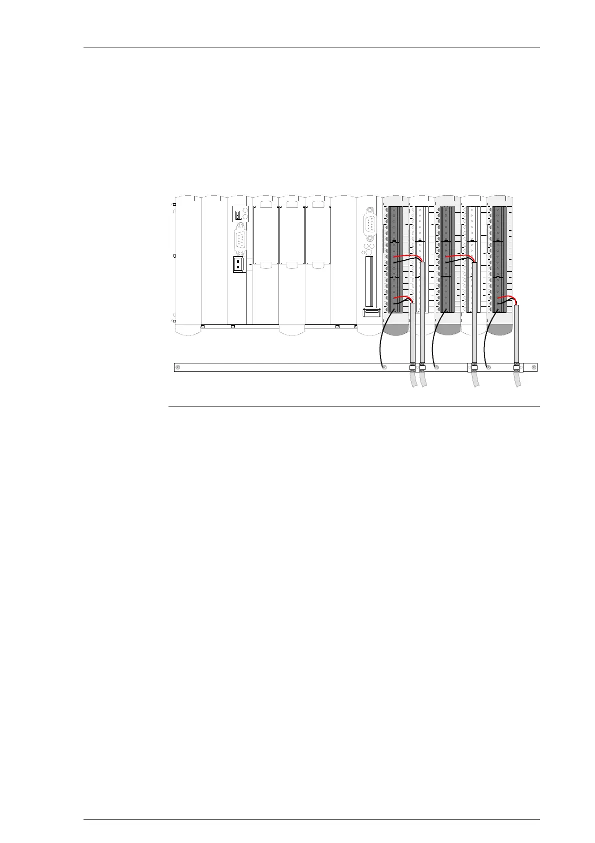
21.4 Connections and wiring
21.4.1 Connection of the shield-rail for analog signals
000102030405060708091011121314151617
GND
AO0
AO1
GND
AO2
AO3
NC
NC
NC
NC
NCNC
NC
NC
NC
NC
NC
NC
GND
000102030405060708091011121314151617
UREF
GND
GND
+
-
AI0
+
-
AI1
+
-
AI2
+
-
AI3
NC
NC
NC
NC
NC
GND
GND
000102030405060708091011121314151617
UREF
GND
GND
+
-
AI0
+
-
AI1
+
-
AI2
+
-
AI3
NC
NC
NC
NC
NC
GND
GND
000102030405060708091011121314151617
UREF
GND
GND
GND
+
-
AI0
+
-
AI1
+
-
AI2
+
-
AI3
AO0
AO1
GND
AO2
AO3
GND
000102030405060708091011121314151617
UREF
GND
GND
GND
+
-
AI0
+
-
AI1
+
-
AI2
+
-
AI3
AO0
AO1
GND
AO2
AO3
GND
GND -connection
against 50 Hz field,
length max. 1 m
shield rail
STATCTRL
DIAG
SI0
0V
+24V
CAN0
RXTX
COMPACT FLASH
USB
ETHCAN1SI1
Connection of the shield-rail for analog signals
21.4.2 Notes on wiring the analog lines
z Analog lines and reference voltage must be connected with a shielded
cable.
z The shield-rail must be connected to the GND-terminal.
z The shield must be placed on the shield rail as shown above.
z To attain optimum interference immunity, analog lines should not be laid
out parallel to strong interfering lines (e.g. lines of converters for mo-
tors).

 Loading...


