System manual CECX / CPU module
14.4 Operating elements and displays
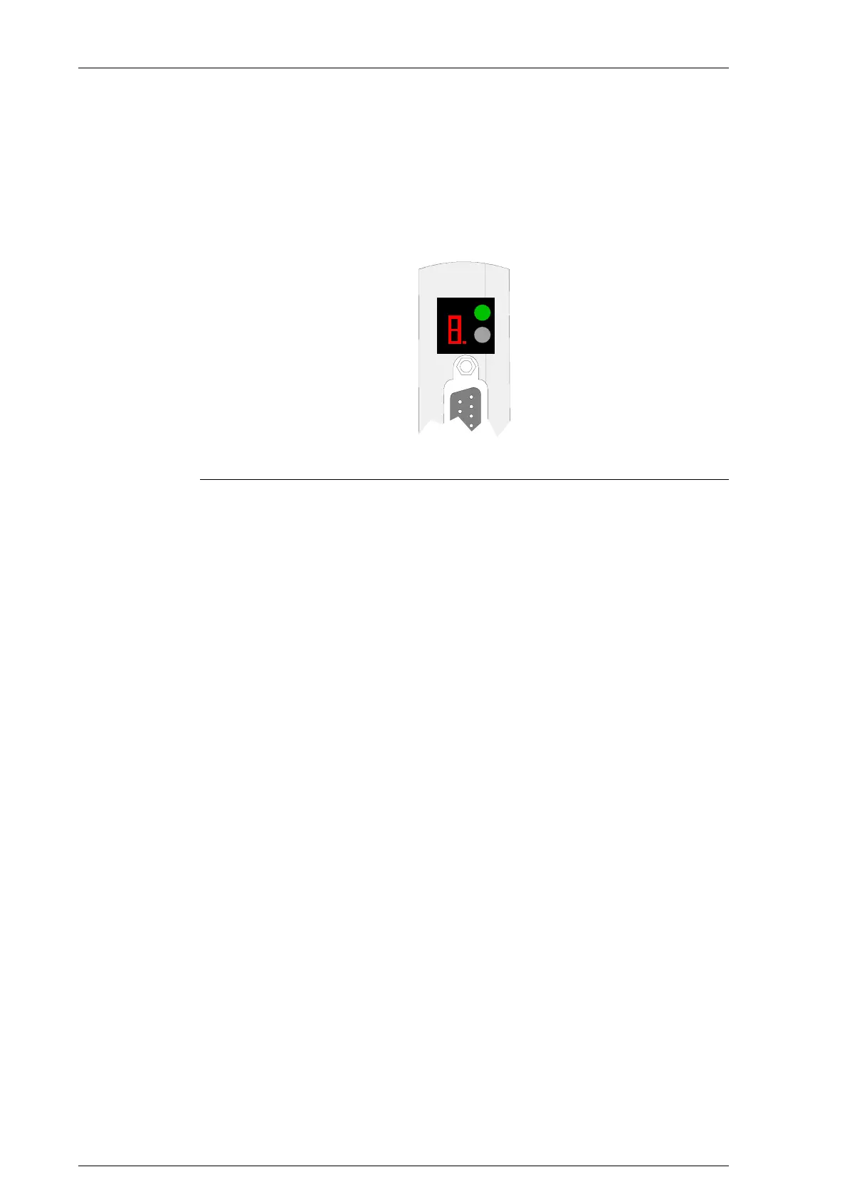
14.4.1 Diagnosis display (Diagnostics)
The diagnosis display shows the states during startup.
PowerCtrl
Diagnostic
Diagnosis display and CTRL key
14.4.2 Power LED (Power)
A green power LED:
LED is lit: Supply voltage is present,
LED is dark No supply voltage.
14.4.3 Program loading button (Ctrl)
The program load key (Ctrl) is located next to the 7-segment display.
The program load key is used to perform various functions, such as switch-
over of operating mode. See chapter Operating behavior.
14.4.4 CAN status LEDs
The module is fitted with two status LEDs (RX- and TX-LEDs at the front
side of the module), which are activated from the Microcontroller.
RX-LED (green): briefly lights up on receipt of a CAN-message
TX-LED (yellow): briefly lights up on transmission of a CAN-message.
CECX-II 14-6

 Loading...


