System manual CECX / Incremental encoder interface module CECX-C-2G2
CECX-II 27-11
27.5 Configuration
27.5.1 General information
A CECX-system needs data for the configuration of system performance,
its I/O-devices and interfaces. The system reads this data during the start-
up operation and allocates them to its components and devices.
Configuration data is created by included configuration tools.
27.5.2 Setting the address
The modules are addressed via the address switch.
It is possible to connect a maximum of
z 8 only CECX-C-2G2 to a CPU module (permissible address switch po-
sitions: 0 – 7),
z 2 only CECX-C-2G2 to a CECX-B-CO (permissible address switch posi-
tions: 0 – 1)
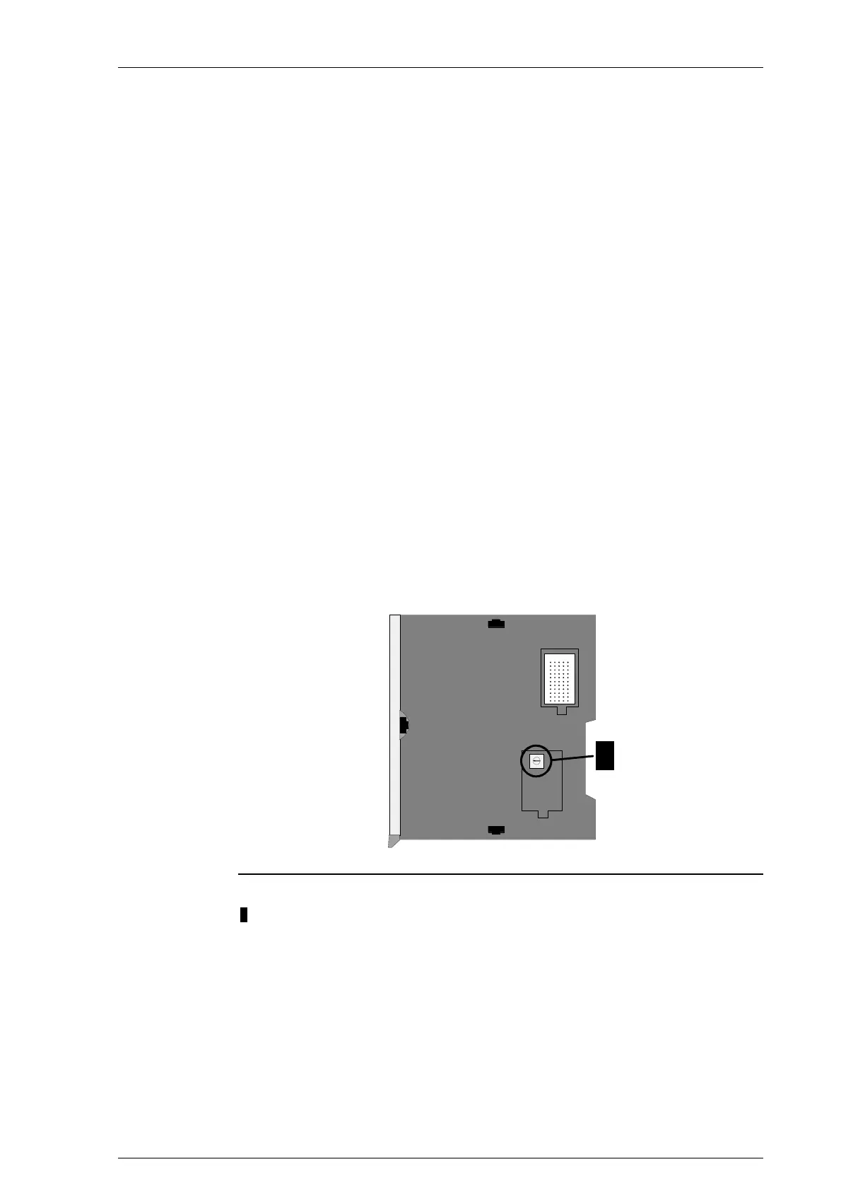
The address switch is located on the right side and underneath the lower
cover. The K-Bus plug is located underneath the upper cover.
0
1
F
2
3
4
5
6
7
8
9
A
B
C
D
E
1
Position of the address switch
1.... Address switch
On leaving the factory all modules are set to address 0 and both covers are
closed.

 Loading...


