System manual CECX / CAN option module CECX-F-CO
CECX-II 30-6
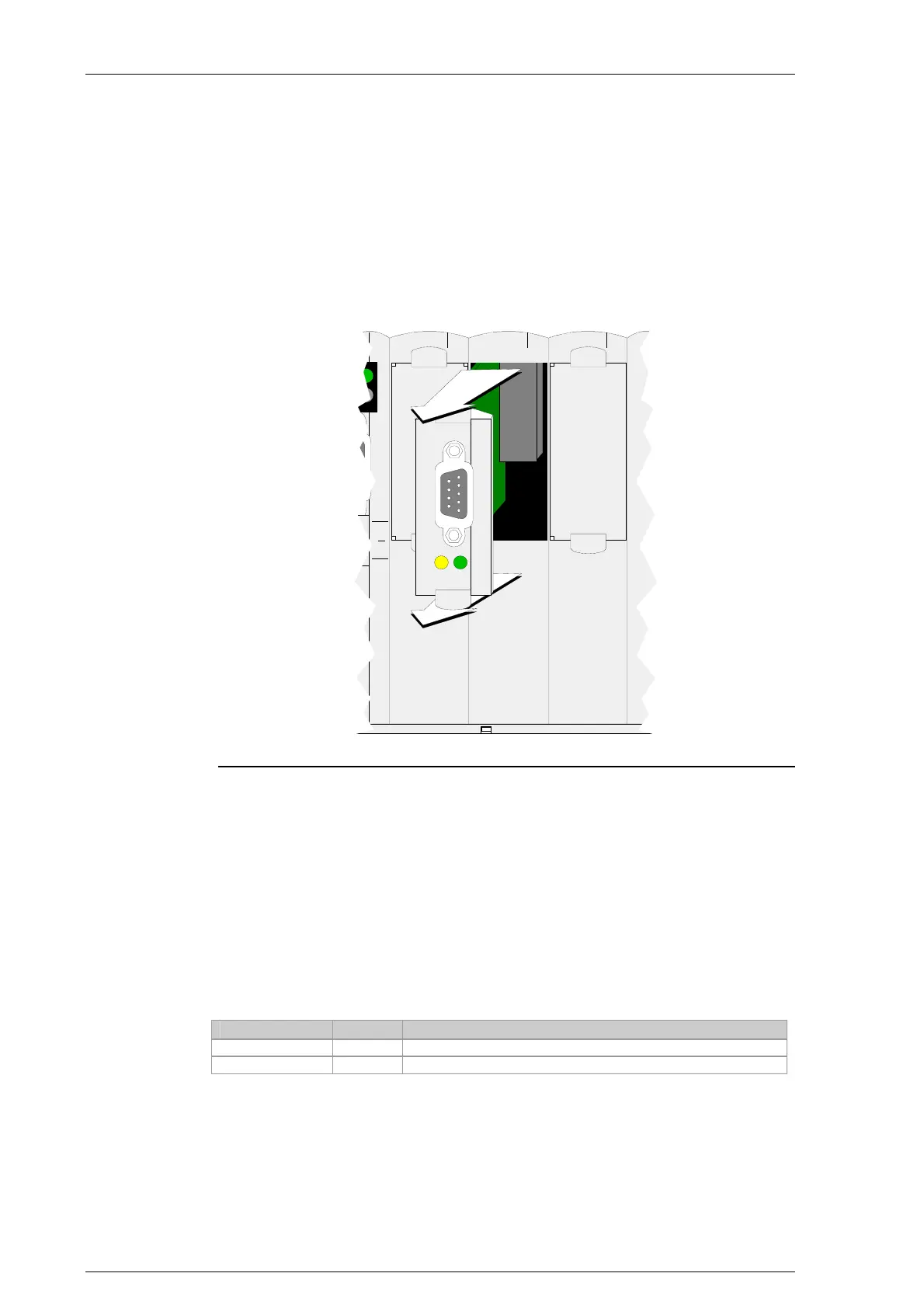
30.4.2 Removing an option module
1) Turn off the power supply.
2) Pull module from the slot.
3) Insert dummy module.
Ethernet
CAN
SI1
CAN
X4
RXTX
X4X3 X5
Removing the CECX-F-CO option module from CP 23x module
30.5 Display and operating elements
30.5.1 CAN-status-LEDs
The module has two CAN-status-LEDs (RX- and TX-LEDs) per CAN inter-
face, which are activated from the Microcontroller.
Name Color Description
RX-LED Green Briefly lights up on receipt of a CAN message.
TX-LED Yellow Briefly lights up on transmission of a CAN message.

 Loading...


