System manual CECX / Introduction
1.4 Notes on this document
Information
If necessary, also adhere to the documentation accompanying the mod-
ules.
1.4.1 Contents of the document
System overview
Start-up description
Operating behavior
Diagnosis
EMC and wiring guidelines
Technical data
1.4.2 Not contained in this document
Programming instruction
Application diagnosis
Firmware description
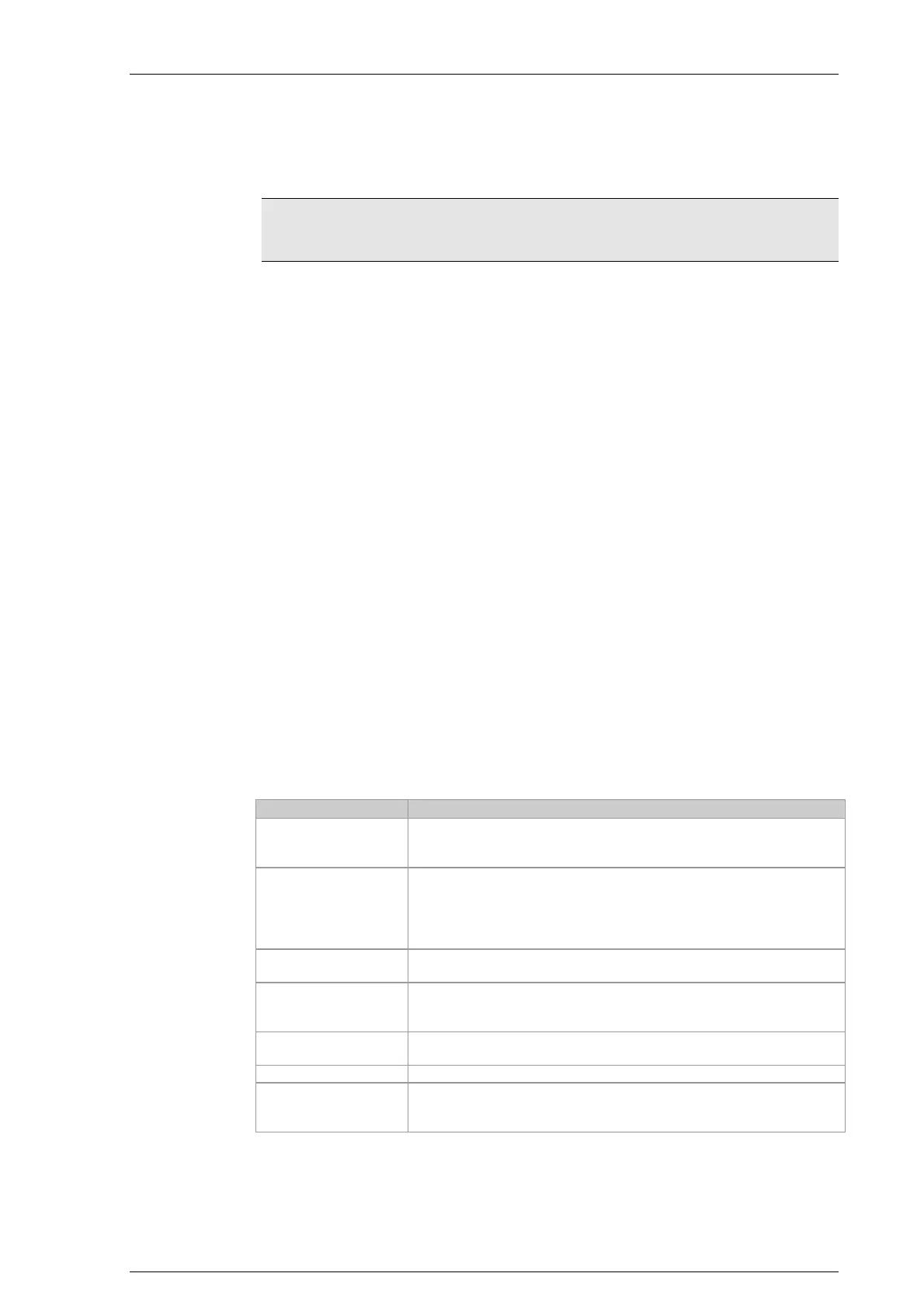
1.5 General product-specific terms and abbreviation
The following product-specific abbreviations are used in this document:
Term/abbreviation Significance
Terminating resistor Resistor for minimizing signal reflections. Terminal resistors must
be installed or joined at the line end of bus segments.
Modules Modules, also termed peripheral modules, establish the connection
with the process. Modules can be plugged into the right-hand side
of the CPU module to extend the range of functions. Signal trans-
ducers and actuators, for example, are linked with the I/O modules.
CPU module Central module of the CECX modular control system.
CANopen A field bus protocol based on CAN which has been standardized as
European standard.
Ethernet Physical protocol and network for linking different devices.
Incremental encoder Encoder
Option module Option modules serve for inserting in CPU modules. Optional mod-
ules for serial interfaces or different field bus links are available.
CECX-II 1-3

 Loading...


