System manual CECX / General assembly and installation instructions
Apart from the following exceptions up to 12 modules of the same kind can
be placed in line on a CPU module or on a bus link module allowing for the
power consumption and the bus load.
CECX-F-PB -V1: Max. 1 pieces can be added on
CECX-F-PB-S-V1: Max. 1 pieces can be added on
CECX-C-2G2:
A maximum of 8 pieces can be added on to a CPU module
CECX-C-2S1: Max. 4 pieces can be added on
CECX-C-2G1:
A maximum of 4 pieces can be added on to a CPU module
4.5 Mounting/dismounting the boards and modules
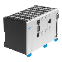
The individual modules are lined up next to each other and connected to
one another via the K-Bus plug. Each line is completely prepared this way
before being installed on the mounting rail (TS 35x7.5) as complete pack-
age.
Preparing for installing on the mounting rail:
1) Unpack modules.
2) Remove all side lids on the K-Bus plug except for the one on the
module to the extreme right.
3) Set address switch with a suitable screwdriver to the setting config-
ured in the application software. The same modules (i.e. those with
the same type designation) must be differentiated by the setting of the
address switch.
!
ATTENTION!
Attention must be given when setting the address switch with the
screwdriver that none of the surrounding components is damaged.
CECX-II 4-3
 Loading...
