1
1 FED/VipWin interface
1.1 Overview
Festo offers the following products for visualising and monitoring processes and sequences in combination
with the Festo CoDeSys controller:
– Front End Displays (FEDs)
Front End Displays from Festo can be connected to the Festo CoDeSys controller via a serial or
Ethernet connection. FED Designer software provides a simple solution for creating projects for FEDs.
Compatible drivers included in the scope of delivery of FED Designer support communication between
an FED and the Festo CoDeSys controller.
– VipWin software
VipWin software installed on a standard PC can be used to create graphic representations of systems
and dynamic process visualisations. Recipe management, reporting, fault transmission and similar
features can be integrated if required. The PC is connected to VipWin via OPC (OLE for Process
Control).
Version 2.3, 31.07.2009, en 0709NH
1.2 Data exchange with the Front End Display (FED)
1.2.1 Basic information on exchanging data with FEDs
Communication between an FED and a Festo CoDeSys controller is configured using "FED Designer"
software.
Note
Use Version 6.07 or later of the "FED Designer" software.
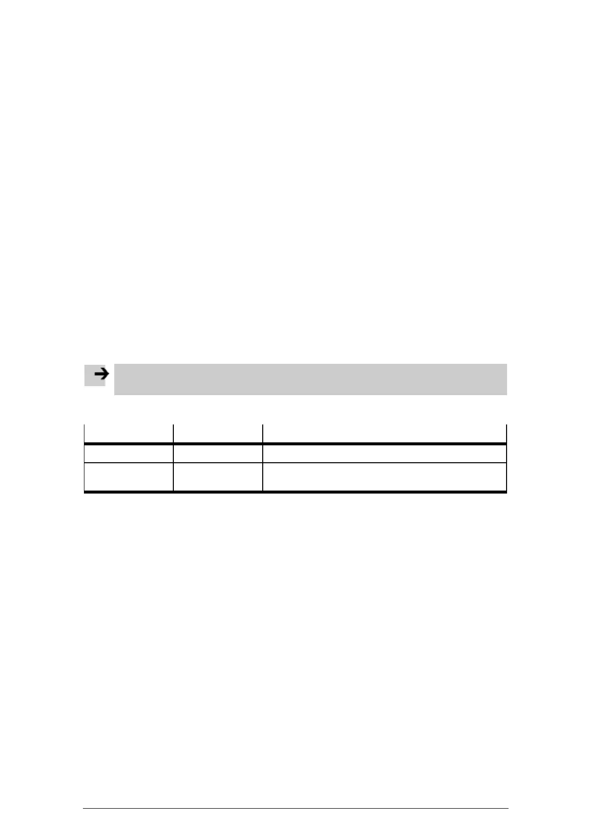
FED Designer offers the following drivers for the Festo CoDeSys controller:
Driver name Connection type Description
CoDeSys ETH Ethernet connection Driver for communicating via TCP/IP (using TCP Port 1200)
CoDeSys Serial connection Driver for serial communication with CoDeSys-compatible
controllers.
1.2.2 Exporting PLC variables (symbol configuration and Tag Editor)
Before communication between the Festo CoDeSys controller and a Front End Display (FED) can be
established, you have to specify which PLC variables must be exchanged between the devices.
– CoDeSys enables the export of PLC variables, which are saved in a symbol file. All PLC variables
from the CoDeSys project are made available.
– The symbol file can be imported using the Tag Editor in FED Designer and used as a tag dictionary so
that FED Designer recognises the PLC variables used in the CoDeSys project.
Creating a symbol file
If you have enabled the function for creating symbol entries in the project options, CoDeSys generates the
symbol file automatically when the project is compiled. You should specify in advance which PLC variables
should be included in the symbol file. The symbol file is saved as a text file (<project_name>.sym) and a
binary file (<project_name>.sdb).
Generate the symbol file as follows:
1. Select the command [Project][Options] in CoDeSys provided by Festo. The "Options" dialog box then
appears.

 Loading...


