System manual CECX / Power supply of modules
5.3 Example power calculation
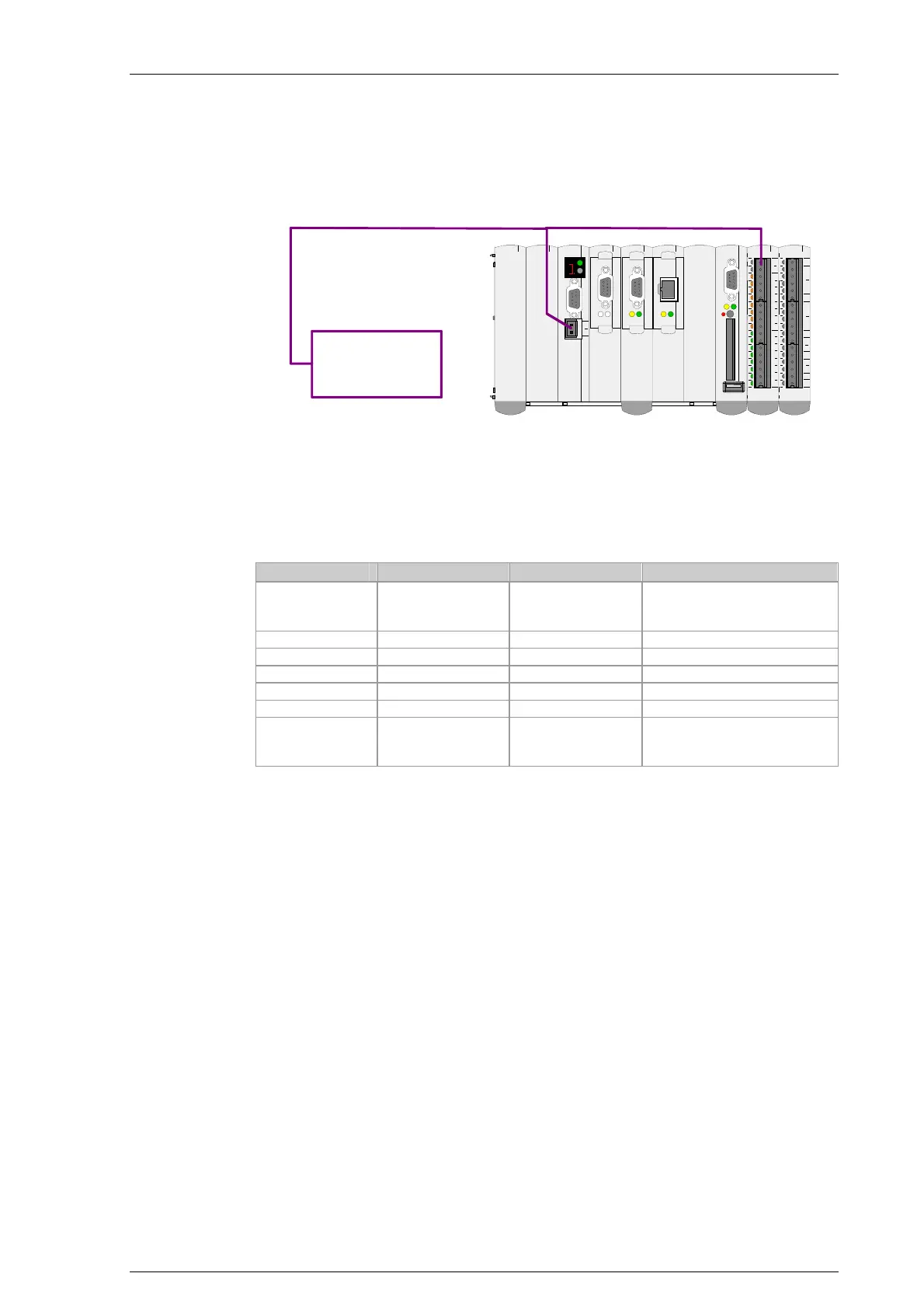
Calculation of the power input required for the following instrumentation.
000102030405060708091011121314151617
UREF
GND
GND
GND
+
-
AI0
+
-
AI1
+
-
AI2
+
-
AI3
AO 0
AO 1
GND
AO 2
AO 3
GND
Pxxxx x-xx xxx
000102030405060708091011121314151617
0V
+24V
DO0
DO1
DO2
DO3
DO4
DO5
DO6
DO7
DI0
DI1
DI2
DI3
DI4
DI5
DI6
DI7
Pxxxx x-x xxxx
SI0
0V
+24V
CAN0
RXTX
USB
ETHCAN1SI1
COMPACT FLASH
PW RCTRL
DIAG
Pxxxx x-xx xxx
ETHE RNE T
SI1
CAN1
RXTX
Power supply
of control
5.3.1 Calculation of the load
The following table lists the power required from the CPU module (called
CPU for short in the following) for the option modules and the add-on mod-
ules. The CPU itself has a consumption of 14 W.
5 V sided / [W] 24 V sided / [W] Comment
CPU module 10 45 Source (this power the CPU
module can provide on the
K-Bus)
Option module 1 0.25 0 Sink
Option module 2 0.25 0 Sink
Option module 3 0.5 0 Sink
Output module 0.4 1 Sink
Analog module 0.3 3.3 Sink
Subtotal 1.7 4.3
Subtotal of the option mod-
ules and the add-on mod-
ules.
The power consumption determined in the subtotal is less than the power
that could be made available by the CPU.
This calculation check is required especially when many add-on modules
are to be operated together with a CPU.
5.3.2 Power supply design
The power supply unit must be designed for:
the power requirement of the CPU, the option modules, the add-on
modules and
the power required for all other connected loads (e.g. outputs that are
supplied by the module).
Power requirement for CPU + modules + assemblies =
14 + 1.7 + 4.3 = 20 W.
CECX-II 5-3

 Loading...


