System manual CECX / Operation and displays
6 Operation and displays
6.1 Setting the module address
The modules in the system are addressed by means of a 16-position ad-
dress switch. This enables all modules within a control package (consisting
of CPU module and a maximum of 12 add-on modules) to be differentiated.
The address switch is located on the side of the modules, underneath the
K-Bus plug. The address must be set prior to the assembly of the package.
See also the project engineering handbook of the components and the
modules.
Information
Modules of the same type must have different address switch positions
within one control package. Different modules in different control packages
may have the same address switch positions.
6.2 Control key (Ctrl)
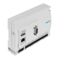
The Ctrl key on the CPU modules is located next to the
7-segment display.
The Ctrl key is used to execute the following functions:
Start application
Stop application
Writing the status report
Deleting of retain data
Deleting the application and the configuration (create default status)
6.3 Power LED (Power)
The green Power LED on the CPU module is located above the CTRL key.
Display:
green illuminated: supply voltage given
dark: no supply voltage
CECX-II 6-1
 Loading...
