System manual CECX / Digital input module CECX-D-16E
CECX-II 15-5
15.4.2 Digital inputs
For the processing of external digital signals, 16 digital inputs of type 1 (ac-
cording to EN 61131-2) are available. They share a common ground poten-
tial but are isolated for the evaluation logic. The switching status "high" is
indicated by green LEDs on the left side of the connector strip.
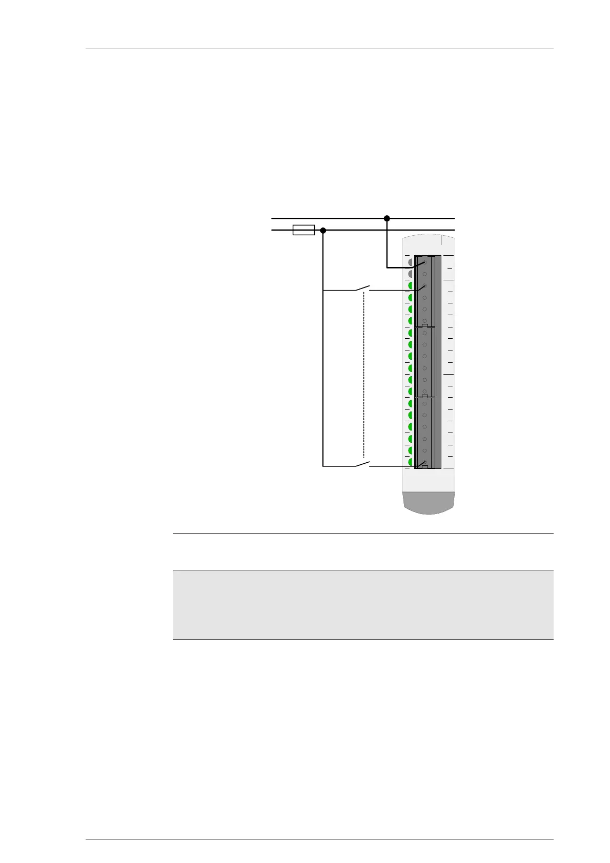
15.4.2.1 Connection example
000102030405060708091011121314151617
0V
n.c.
DI0
DI1
DI2
DI3
DI4
DI5
DI6
DI7
DI8
DI9
DI10
DI11
DI12
DI13
DI14
DI15
Pxxxxx-xxxxx
0 V
24 V
10 A
Connection example for digital inputs
Information
• The reference potential for the isolated digital inputs is the 0 V terminal
that is located on the front side.
• For operation of the digital inputs the 0 V- terminal located on the front
side must be connected.
15.4.2.2 Status display
16 green LEDs to indicate the signal status:
z LED is lit: Input on "1"
z LED is dark Input on "0"

 Loading...


