System manual CECX / Digital output module CECX-D-14A-2
CECX-II 16-11
16.6.2 Switching inductive loads
The module contains no internal freewheeling diode to take up the inductive
energy when switching off the inductive loads.
The inductive load capability for each channel is 1 J at 0.2 Hz.
The inductive energy is transformed into heat by the switching transistor. It
sets itself a voltage of -60 V. This allows for a swifter breakdown of the en-
ergy than would be possible when using the freewheeling diode.
Information
The load capacity of the outputs for inductive loads can be raised by adding
an external freewheeling diode, which will, however, significantly increase
the switch-off time.
In the case of high load currents, higher values of inductance or greater
switching frequency, a freewheeling diode must always be used.
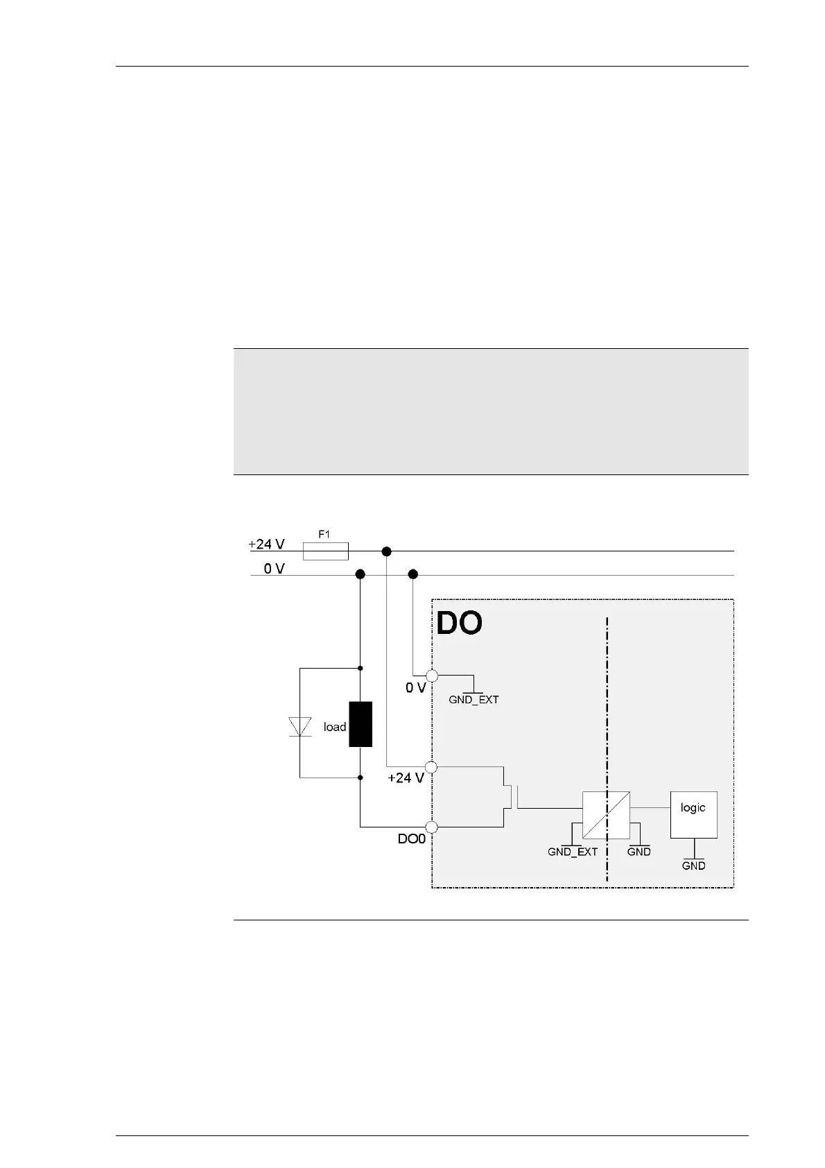
16.6.2.1 Connection diagram
Schematic diagram for the use of a freewheeling diode
16.6.3 Parallel arrangement of outputs
Outputs can be shunted parallel; two outputs can be shunted parallel.

 Loading...


