System manual CECX / Digital input/output module CECX-D-6E8A-PN-2
CECX-II 18-10
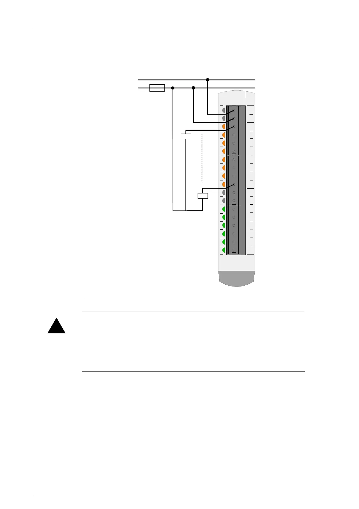
18.4.4.1 Connection example
000102030405060708091011121314151617
0V
+24V
DO0
DO1
DO2
DO3
DO4
DO5
DO6
DO7
0V
+24V
DI0
DI1
DI2
DI3
DI4
DI5
Pxxxxx-xxxxx
0 V
24 V
F1
Connection example for digital outputs
!
CAUTION
• Wrongly plugging the supply terminal blocks by one position down-
wards can lead to the destruction of the module.
• Even if one of the 0V pins is not connected, the digital outputs still func-
tion. However, the LEDs do not light up in this case and the status of
the digital outputs is not correctly indicated.
18.4.4.2 Status display
8 orange LEDs to indicate the signal status:
z LED is lit: Output HIGH
z LED is dark Output LOW

 Loading...


