System manual CECX / Analog input/output module CECX-A-4E4A-A
CECX-II 22-6
22.4.3 Analog inputs
There are 4 analog inputs with 14-bit resolution available.
For further information on wiring and shielding of the analog outputs: See
System manual.
!
WARNING!
Unintentional switching on of a drive possible!
• If the power supply for the modules is not switched on, but a voltage is
applied to the analog inputs (e.g. by the external supply of an encoder),
there may still be a voltage on the analog outputs.
This enables drives to be switched on even though they have not re-
ceived an ON-command.
Remedy: The drives must only switch after the activation of an enable
output. This must only be switched on after the system startup has
been completed (e.g. via the output of a digital output module)
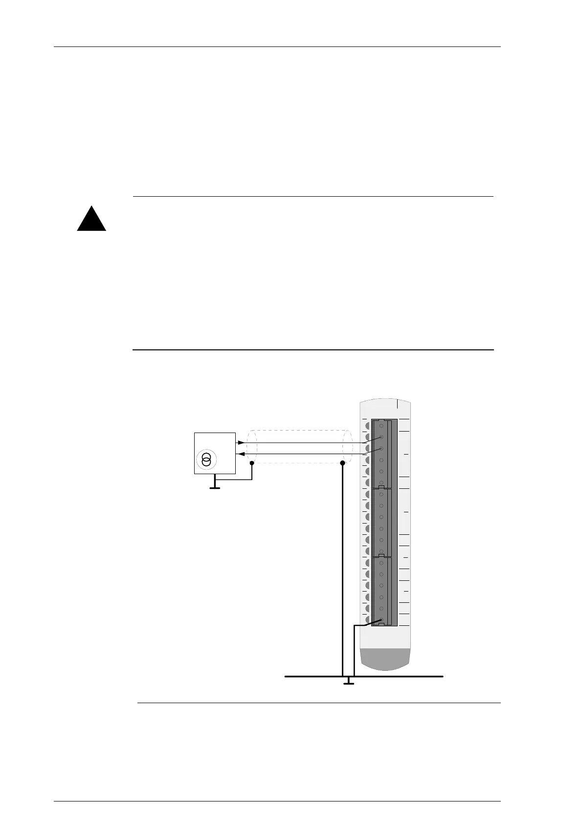
22.4.3.1 Connection example
000102030405060708091011121314151617
NC
GND
GND
GND
+
-
AI0
+
-
AI1
+
-
AI2
+
-
AI3
AO0
AO1
GND
AO2
AO3
GND
shield rail
I
out
Sensor
0 - 20 m A or
4 - 20 m A
Connection example for analogue inputs

 Loading...


