System manual CECX / SSI Interface module CECX-C-2G1
CECX-II 29-7
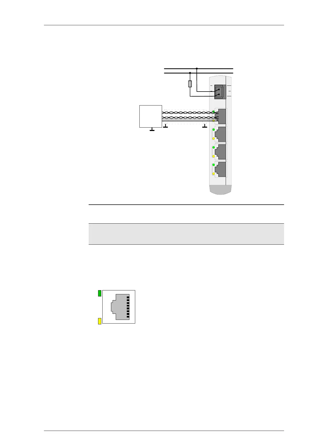
29.5.2.1 Connection example
0V
+24V
0001
SSI0SSI1SSI2SSI3
CK+ / CK-
DI+ / DI-
0 V
24 V
transducer
24 V
0 V
DI+/DI-
CK+/CK-
F1
Connection example for transducer
Information
The voltage drop between the supply terminal and the voltage output on the
SSI interface socket amounts to 1 V at 250 mA.
29.5.2.2 Pin assignment
PIN-No. Name
1 n.c.
2 n.c.
3 DI+ Data input +
4 CK- Clock input -
5 CK+ Clock input +
6 DI- Data input -
7 24 V Transducer supply output
81
8 0 V Transducer supply output

 Loading...


