System manual CECX / System overview
3.1.2 Display of data
3.1.2.1 CoDeSys
To enable the data of the CECX modular control system to be operated and
monitored does not require an additional tool apart from the CoDeSys pro-
gramming system (data are displayed on the CECX modular control system
via LEDs, display or the activated visualization).
The Front End Display (FED) is available for the visualization and monitor-
ing of processes and sequences in connection with the CECX modular con-
trol system.
3.1.2.2 Linking of Front End Displays (FED)
Festo front
end displays can communicate with t
he CECX modular control
system via a serial connection or an Ethernet connection.
The scope of supply from the designer of the FED includes appropriate
drivers which support the easy variable exchange on the basis of the sym-
bol files (see also online Help of CoDeSys).
Attention:
Is in CECX a variable declared as BYTE, WORD or DWORD an bit wise
access via the FED is not possible. In general it is recommended to access
via variable names.
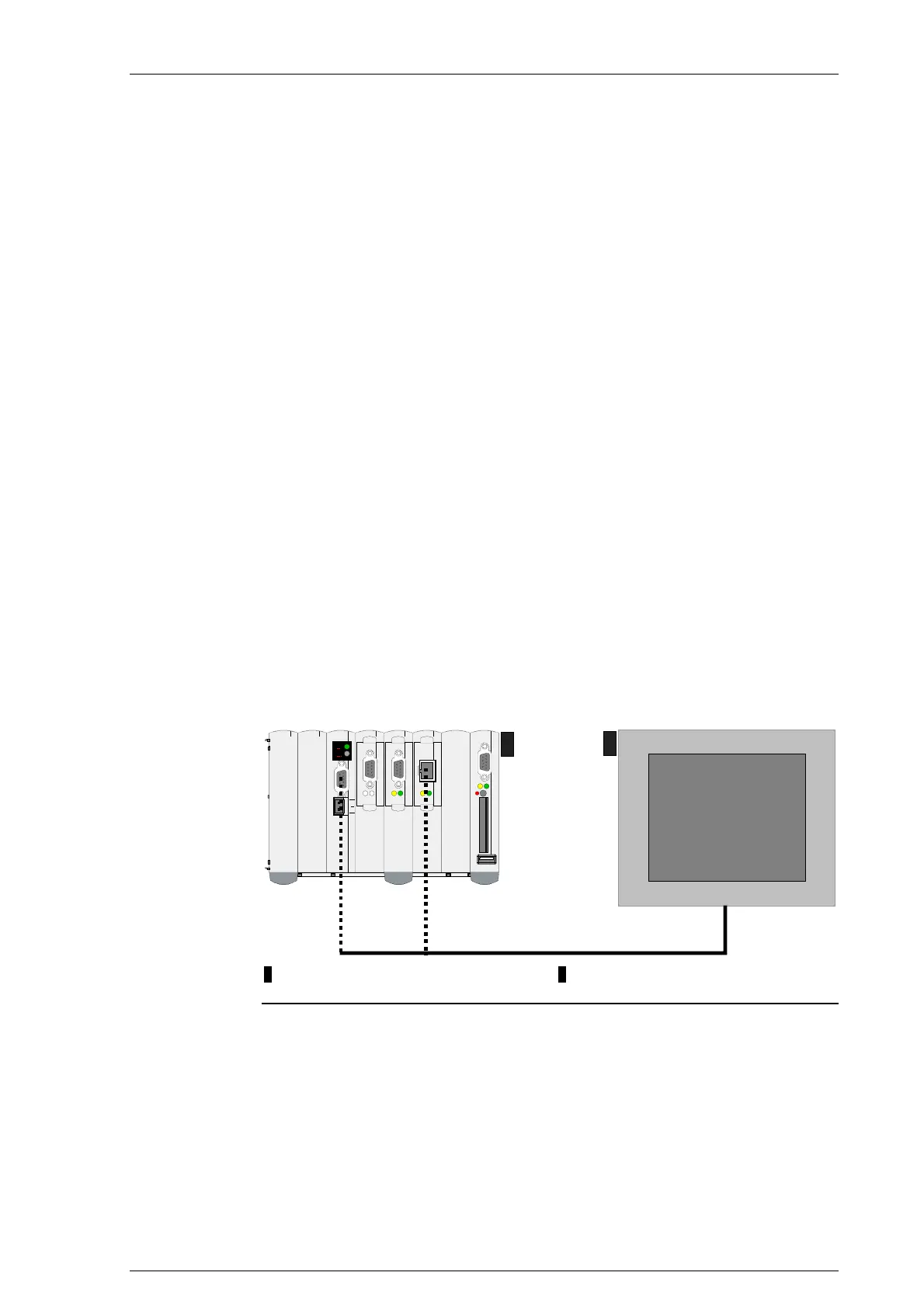
CAN 0
RXTX
1 2
RS-485-A
Ethernet
1........ CECX modular control system 2.........Front End Display FED
CECX modular control system and FED
RS-485-A connection cable
This cable can be ordered from Festo.
Designation: NEBC-S1G15-K-2.5-N-B-S1G9-V, Order no. 563782.
See also chapter 7.6 "Connecting an FED".
CECX-II 3-3

 Loading...


