P L U G P I N O U T S C H A P T E R 4
Push To Talk (PTT) Input
The External Control (X2) connector has two PTT input connections as seen in Table 1 above. Pin 11
works in all modes, while Pin 10 works only in voice modes. Pin 11 is recommended for most applications.
PTT is activated by grounding to Pin 15 either of the two respective pins.
Mute Receiver
The External Control (X2) connector has a pin dedicated to muting the receiver for multiple transceiver
operation. Simply ground Pin 12 to Pin 15 to activate the software MUT (Mute) control. Note that this does
not disconnect the coaxial connector from the receiver. External antenna switching is necessary to ensure
that high power signals are not sent directly to the SDR-1000 receiver front end.
External Linear Amplifier Keying
External linear amplifiers may be keyed using Pin 7 on the External Control (X2) connector. Most
amplifiers are switched by grounding its keying input. Connect Pin 7 (PTT Output) to the hot lead of keying
input and Pin 15 to the amplifier ground. This output uses an open collector Darlington transistor switch
that is rated at 500mA, 50VDC maximum.
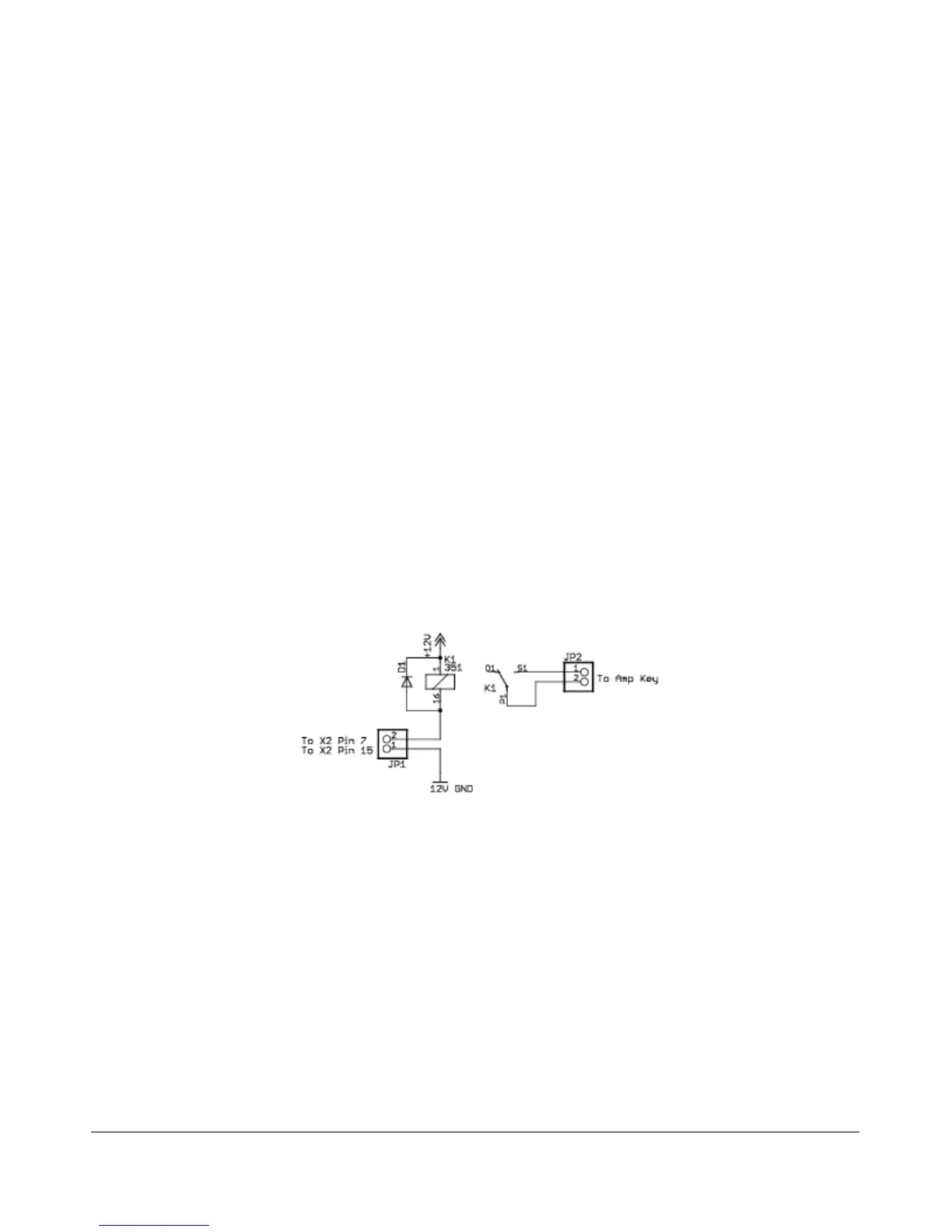
To ensure that your amplifier keying circuit does not damage the Darlington transistor switch, insert the
circuit shown in the figure below between Pins 7 and 15 on X2 and your amplifier.
Figure 1: Protective PTT Circuit Between SDR-1000 and Amplifier
Universal Controller Board for Antenna and Transverter Control
The Universal Controller Board (UCB) is a customer developed and supplied accessory that connects to the
External Control (X2) connector. It allows automatic software control of up to 16 antennas and/or
transverters.
The Universal Controller Board is an extension of the SDR-1000 to enable additional control of external
devices by the radio. The SDR-1000 X2 connector provides 6 open collector output pins for user defined
functions. The purpose of the UCB is to accept data from the SDR-1000 via the X2 connector to be loaded
into a 16X16 memory matrix on the UCB. Pins 1 through 4 of the X2 connector are used as an address field
by the UCB to address one of 16 registers within the memory matrix. Each one of these UCB registers has
9 FlexRadio Systems