F R O N T C O N S O L E C H A P T E R 7
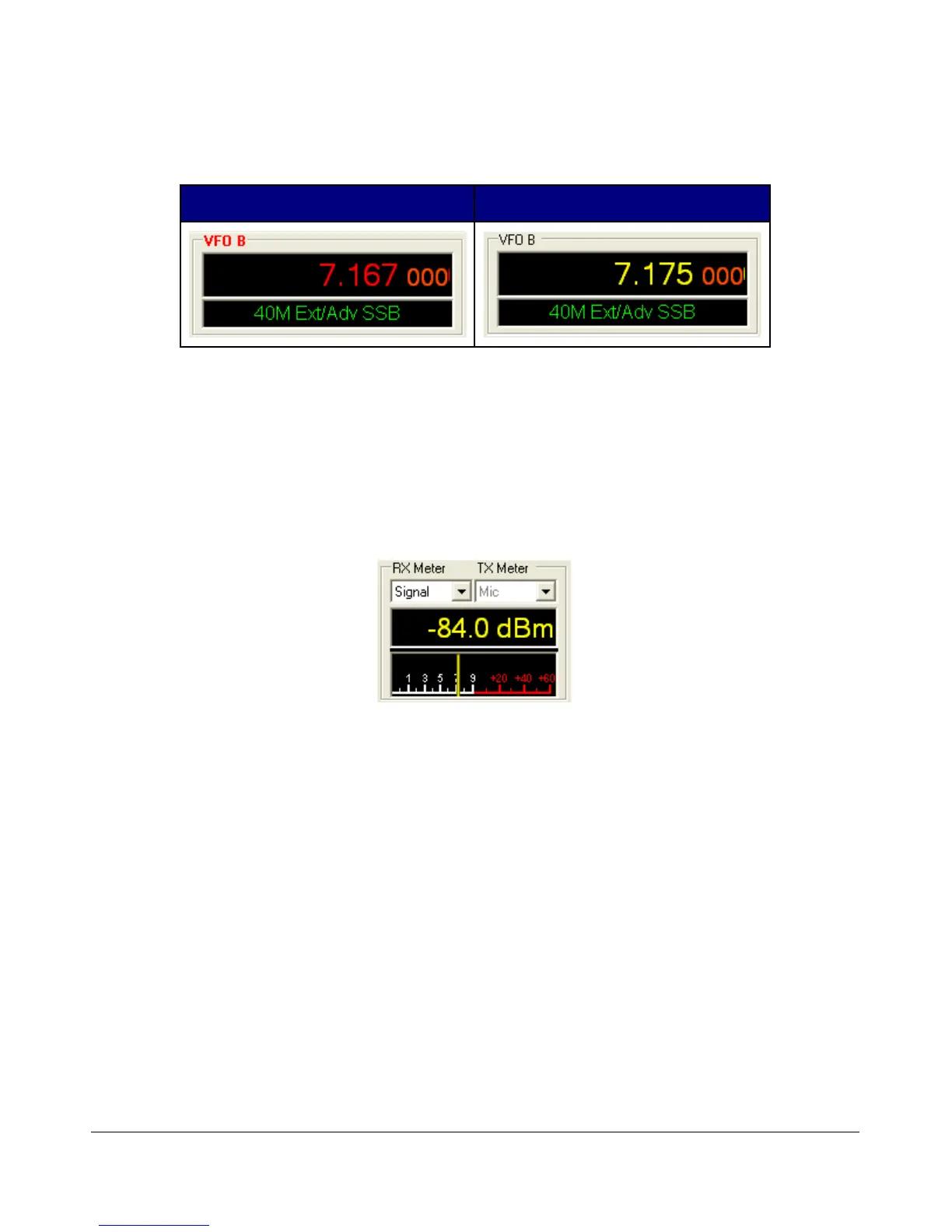
(3) VFO B
Split Transmit Frequency Sub RX Frequency
Figure 28: VFOB
The operation of VFO B is similar to that of VFO A. However, VFO B is used only in specific instances.
When operating split (SPLT button under VFO), VFO B determines the transmit frequency (both “VFO B”
and the frequency are displayed in red). When activating the second receiver (Sub RX button under Sub
RX), VFO B determines the second receiver’s frequency, which is displayed in yellow. Otherwise, it can be
viewed as a storage container to copy VFO data to and from VFO A (see the VFO Controls section below).
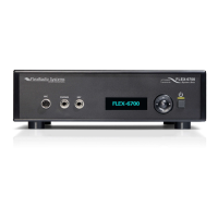
(4) Multimeter
Figure 29: Multimeter
The multimeter functions as another way of feeding information back to the user. The two drop down boxes
at the top offer an independent selection of RX and TX multimeter options.
The text display below the meter selections shows the digital data for either the receiver or the transmitter
(Signal strength in the screenshot above). The display at the bottom of this section shows the data
graphically as an edge meter. A bar graph display can be selected instead (see the Appearance section in the
next chapter).
RX Meters
Signal (Signal Level): Calculates the true RMS power in dBm of the current signal within the
passband.
Sig Avg (Signal Average): Calculates the true RMS power in dBm of a time-averaged signal
within the passband.
41 FlexRadio Systems