P L U G P I N O U T S C H A P T E R 4
16 bits, of which any combination can be operational. Each bit in a register corresponds to a relay that will
be picked.
Enclosure Microphone Connector
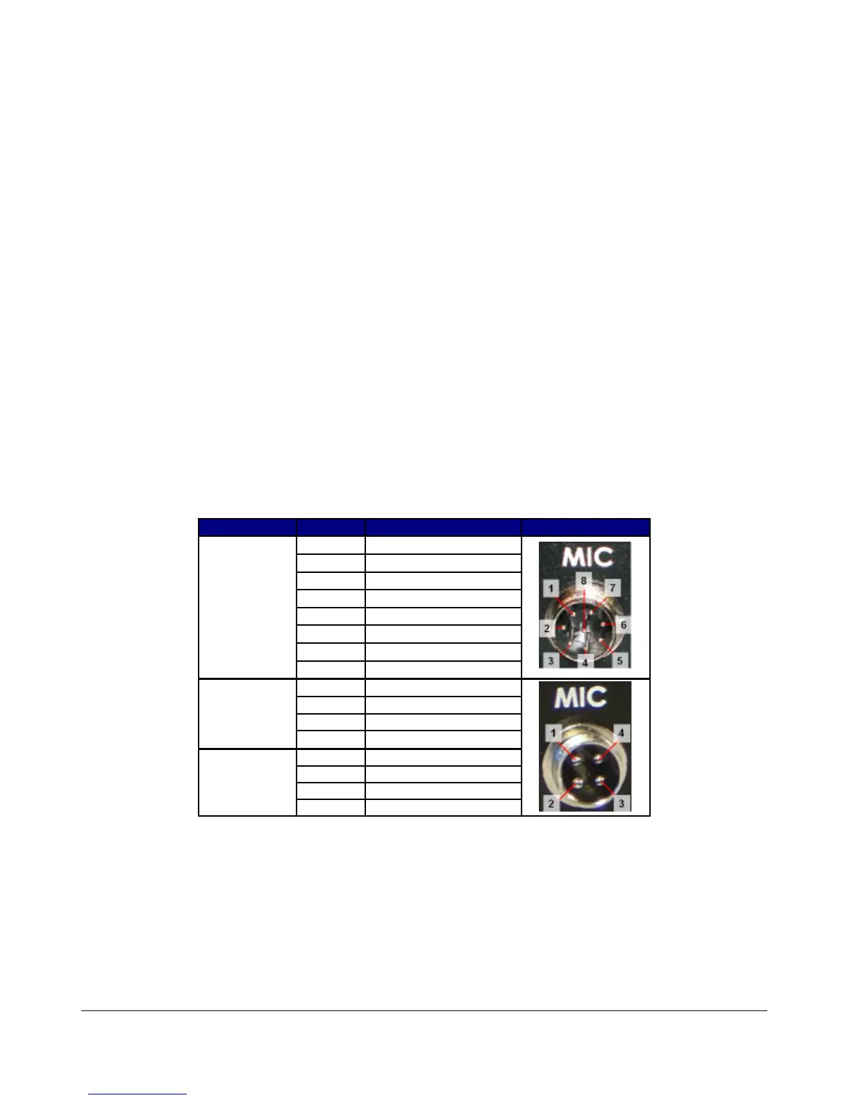
A front panel connector is provided for microphone and push-to-talk (PTT) input. Depending on when your
radio shipped, the connector will be a 4 or 8 pin connector. See the table below for the pinouts for each of
these connectors. The PTT input must provide a contact closure to ground to activate the transmitter.
The 8-pin microphone configuration offers the ability to connect a balanced microphone through the front
panel connector. Keep in mind that it is possible to plug a microphone directly into either of our
recommended sound cards (Delta-44 and Edirol FA-66). They both offer ¼” connectors and the Edirol FA-
66 has true balanced inputs along with XLR connectors and adjustable Mic Preamps.
Radios shipped after January 11, 2006 have an 8-pin connector. Radios shipped before that date have a 4-
pin connector, but the wiring configuration of this connector has been modified on all radios shipped after
February 4, 2005 from those shipped before that date. The following table shows the pin connections and
the wiring configurations.
Table 3: Microphone Connector Configurations
Ship Date Pin # Signal Diagram
After
Jan 11 2006
1 Not Connected
2 Not Connected
3 Not Connected
4 Not Connected
5 Chassis GND (Shield)
6 PTT (+)
7 Mic (–)
8 Mic (+)
Before
Jan 11 2006,
After
Feb 4 2005
1 Mic (+)
2 Mic (-)
3 PTT (+)
4 PTT (-)
Before
Feb 4 2005
1 Ground
2 Microphone Audio
3 Push To Talk
4 No Connection
We recommend use of the Heil microphones, especially the PR series; however, the HM-10 and Goldline
microphones will also work well with the SDR-1000.
Use the procedure found in the Voice Transmission Operation section in order to match the microphone
appropriately with the sound card and the DSP.
10 FlexRadio Systems
 Loading...