F R O N T C O N S O L E C H A P T E R 7
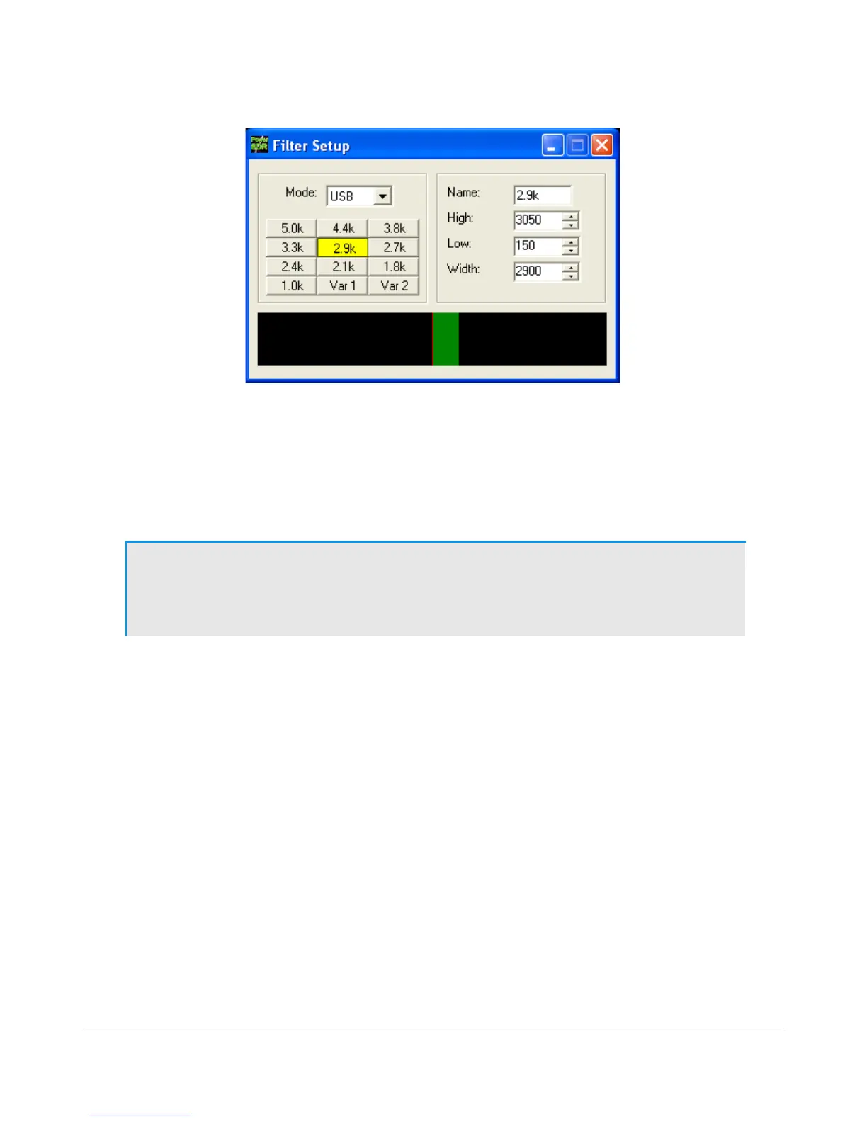
Figure 34: Filter Setup Screen
On the left, select the Mode for which to setup the filter and select the filter button to change. Then on the
right adjust its settings. An indication of the filter is displayed in the lower section of this screen. When
done, you can select another button and/or mode to change the filter for. When finished, just close the Filter
Setup Screen. To revert back to the default settings, right click on a filter button, select Reset to Defaults
and click Yes.
Note: Although there are 3 groups of mode-dependent default filter settings, you
can customize the labeled filter for each mode independently. E.g. you
can have different filters for LSB and USB, for FMN and AM, etc.
Variable Filter Buttons
The variable filter buttons Var 1 and Var 2 offer two separate filters, each of which can be adjusted with
the Low, High, Width, Shift and Res controls described below as well as the mouse. The Panadapter
display setting is good for visualizing changes to variable filter controls
Low: Selects the low cutoff frequency for the filter. The value is the plus or minus offset from the
center frequency as shown in the VFO display. Note that in lower side band modes (LSB, CWL and
DIGL) this value can be negative.
High: Selects the high cutoff frequency for the filter. Note that in lower side band modes (LSB,
CWL and DIGL) this value can be negative.
Width: Widens the filter as the slider is moved right, and narrows the filter as it is moved left.
Shift: Shifts the selected filter passband up or down from its normal center frequency. This can help
to eliminate interference caused by signals in close proximity of the received signal. After a variable
filter (Var 1, Var 2) has been shifted you can use the IF->V button to translate a filter shift to a
new VFO frequency (see the VFO Controls section below)
46 FlexRadio Systems