F R O N T C O N S O L E C H A P T E R 7
Phase
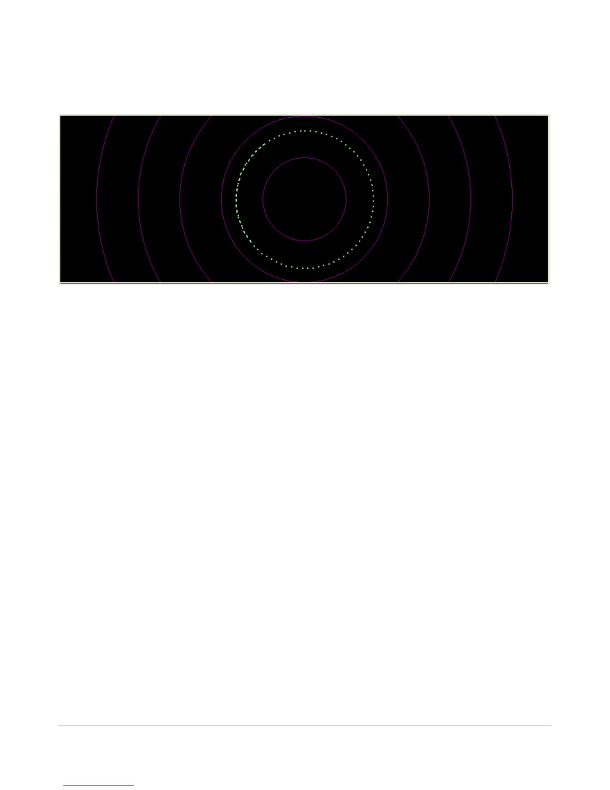
Figure 45: Phase Display
The Phase Display maps the filtered I and Q (Left and Right) channels to the X and Y coordinate planes.
This is useful for making sure the two channels are 90 degrees out of phase as they should be. There is also
a Phase2 Display that maps the unfiltered data directly from the sound card. When a continuous carrier
signal is received, the unfiltered data in the Phase2 Display should produce as near to a perfect circle as
possible. If the circle distorts into an oval or a straight line, the input phase is off balance which would
indicate a connection or hardware problem.
Off
In this setting the display is turned off. It is mainly used for debugging purposes, but can also be used with
slower systems to decrease the CPU load to more reasonable levels.
[The rest of this page has been left blank intentionally]
56 FlexRadio Systems