GE MEDICAL SYSTEMS PROPRIETARY TO GE
D
IRECTION 2294854-100, REVISION 3 LOGIQ™ 9 PROPRIETARY MANUAL
Chapter 5 Components and Functions (Theory) 5-19
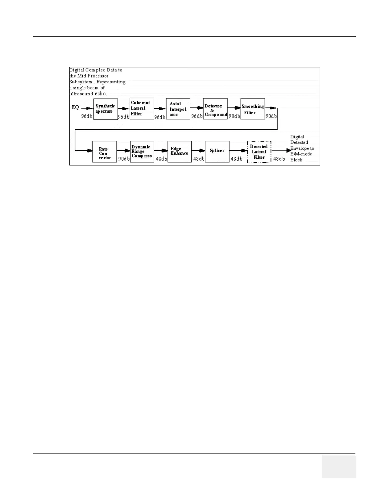
5-3-5-2Receive Signal Processing (cont’d)
• Synthetic Aperture - In synthetic aperture mode, multiple firings from different sets of transducer
elements are summed to form a single coherent vector. Control of the summing process is provided
by scan control parameters. The accumulate and synthesis (sum) operations are also used for B-
Flow data processing.
• Coherent Lateral Average (Shared Service) - The lateral average block applies a 2-point or 3-
point box-car average from vector to vector. In 1:1 imaging mode, this can produce some SNR gain
and restrict lateral spatial bandwidth prior to detection. More importantly, the lateral averaging is
needed in 2:1 mode to smooth out the differences between Left and Right beams. This feature is
not required until the shared service release.
• Axial Interpolator - The axial interpolator function is applied along each vector to double the data
sampling rate prior to envelope detection. This is done to prevent axial signal aliasing after the
nonlinear detection process. The system provides an enable signal to turn on this 2x axial
interpolation.
• Detector and Compounder - The purpose of the detector is to compute the polar magnitude of the
complex I/Q data. The detector output is passed into a vector compounder which can reduce
speckle by summing up multiple receive vectors along each scan line. The vector compounder can
be used in conjunction with the synthetic aperture block. That is, a vector finally output from the
compounder may be the accumulation of up to 32 input vectors (4 vectors compounded – each of
which being an accumulation of 8 vectors in the synthetic aperture block.). The vector compounder
shall support bypass vectors and accumulated vectors in the same scan sequence, with gain only
applied to the accumulated vectors.
• Smoothing Filter - The smoothing filter serves primarily as an anti-aliasing filter before rate
conversion, though it may also be viewed as an axial compounding device for speckle reduction.
• Rate Converter - The purpose of the rate converter is to reduce the size of the received vector to
that allowed by the PC backend. The rate conversion shall be by means of a cubic interpolator.
Each output sample is produce from the nearest four input range samples. The coefficients used
are a function of the output samples fractional position between input range samples. The rate
converter FIFO and associated counter shall support a 36 cm display depth.
• Dynamic Log Compress - The purpose of the dynamic log compress is to map the input dynamic
range (90 dB) to a display dynamic range (48 dB) suitable for human perception. The input dynamic
range is reduced, while the input noise threshold is raised with increasing depths. The goal is to
improve image perception degraded by signal loss at greater depths. The dynamic range
compression shall provide a precision of 0.25 dB in offset and range (gain).
Figure 5-16 Receive Signal Processing