GE MEDICAL SYSTEMS PROPRIETARY TO GE
D
IRECTION 2294854-100, REVISION 3 LOGIQ™ 9 PROPRIETARY MANUAL
Chapter 8 Replacement Procedures 8-105
8-24-4 Release Lock Removal Procedure
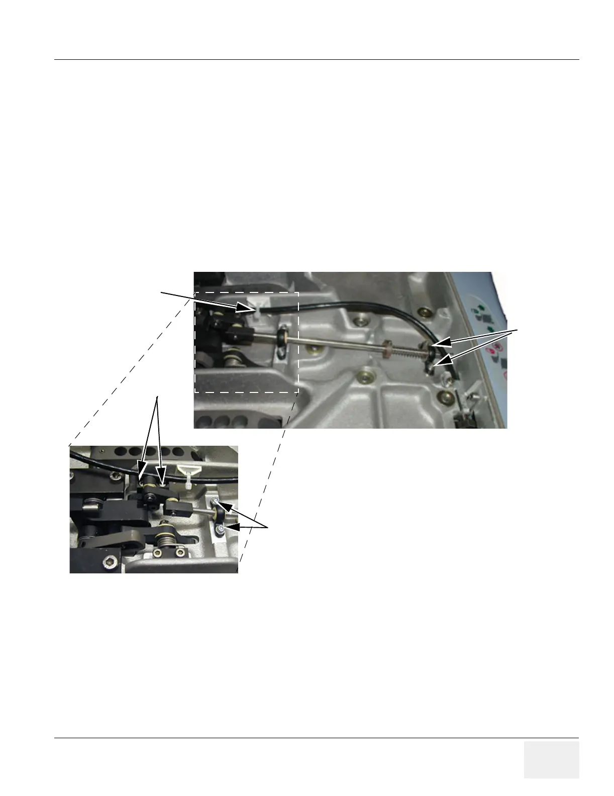
1.) Unscrew 8 mm nut behind XY-Handle.
2.) Unscrew 2 hexagon screws (3 mm).
3.) Unscrew 4 hexagon screws (2,5 mm).
4.) Remove Release Lock Assembly.
8-24-5 Release Lock Installation Procedure
1.) Install Release Lock Assembly.
2.) Fasten 6 hexagon screws.
3.) Fasten nut behind XY- Handle.
4.) Install XY-Handle as described in XY-Release Handle Installation Procedure on page 8-101.
5.) Install Operator Panel as described in Operator Panel Installation Procedure on page 8-112.
Figure 8-115 Release Lock Assembly
Strap
Screws
Screws
Screws