GE MEDICAL SYSTEMS PROPRIETARY TO GE
D
IRECTION 2294854-100, REVISION 3 LOGIQ™ 9 PROPRIETARY MANUAL
Chapter 5 Components and Functions (Theory) 5-41
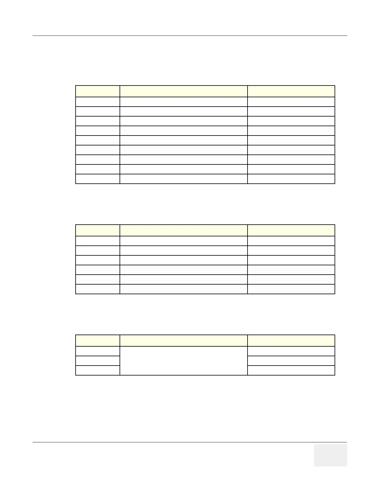
5-7-5 Inputs
DC Voltages
Video Input Signals
Audio Input Signals
Table 5-20 DC Input Voltages
Input Description Connection from
+3.3 VDC Input DC Voltage DC Power Supply > Backplane > J32
+5 VDC Input DC Voltage DC Power Supply > Backplane > J32
+10 VDC Input DC Voltage DC Power Supply > Backplane > J32
+15 VDC Input DC Voltage DC Power Supply > Backplane > J32
-15 VDC Input DC Voltage DC Power Supply > Backplane > J32
+6 VDC (analog) Input DC Voltage DC Power Supply > Backplane > J32
–5 VDC (analog) Input DC Voltage DC Power Supply > Backplane > J32
+5 VDC Input DC Voltage Backend Processor > J17
+12 VDC Input DC Voltage Backend Processor > J17)
Table 5-21 Video Input Signals
Input Description Connection from
SVGA Video Signal to External I/O PC2IO (Connector J16)
SVHS Video Signal to VCR & External I/O PC2IO(Connector J16)
SVHS Video Signal to MBD (IMP) VCR (Connector J11)
Luma Video Signal to B&W Printer and External I/O PC2IO (Connector J16)
Comp. Video Video Signal to External I/O PC2IO (Connector J16)
Comp. Video Video Signal to MBD (IMP) Color printer
Table 5-22 Audio Input Signals
Input Description Connection from
Two channel audio
Audio signals, summed and distributed
MBD (IMP)
Two channel audio VCR
Two channel audio BEP
 Loading...


