GE MEDICAL SYSTEMS PROPRIETARY TO GE
D
IRECTION 2294854-100, REVISION 3 LOGIQ™ 9 PROPRIETARY MANUAL
Chapter 8 Replacement Procedures 8-127
8-32-5 External I/O Installation Procedure
1.) Install the new External I/O Assembly by pushing it into the socket on the rear wall of the Internal I/
O and fastening it with the Phillips screw.
2.) Fasten it to the chassis leg with the two screws.
3.) Mount the Right side as described Section 8-2-2 on page 8-5.
4.) Mount the Upper Rear Cover as described in Section 8-2-3 on page 8-7 and the Lower Rear Cover
in Section 8-2-6 on page 8-10.
5.) Connect all cabling to and from the External I/O. Remember: There are two connectors on the
bottom side of the box. These two are identical in size and pinout. The left one is manufacture
power cycle testing and the one on the right is for the modem connection. If they are mixed up the
system will experience power up problems as soon as the modem powers on.
6.) Turn ON the Main Breaker and boot up the system as described in Section 4-3-1 on page 4-2.
7.) Do functional check-out as described.
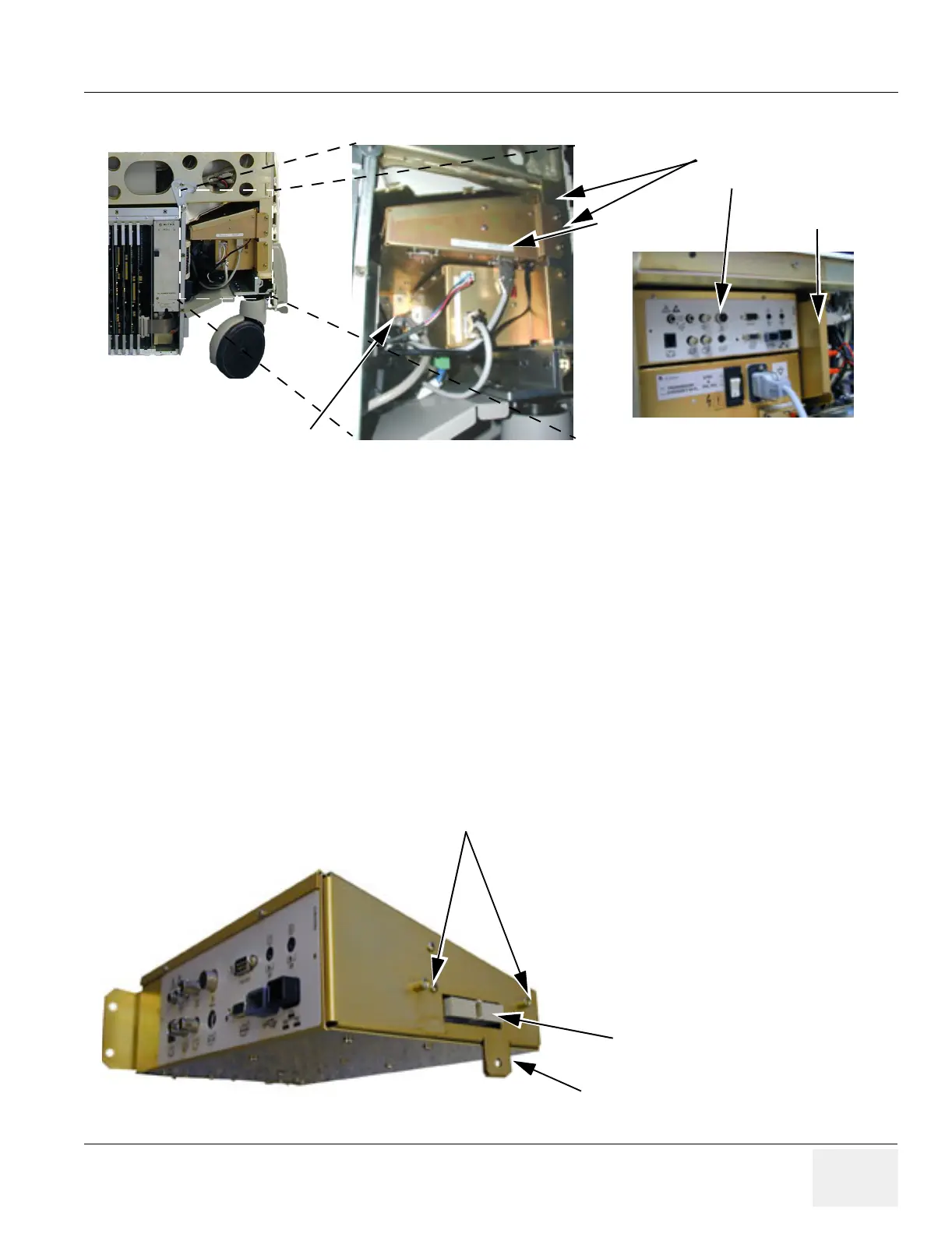
Figure 8-137 External I/O Location
Figure 8-138 External I/O Installation
Screws on chassis leg
Screw on Internal I/O
External I/O rear side
Internal I/O
External I/O
Connector on External I/O
Flange for fastening External I/O to
Internal I/O.
Centering pins