GE MEDICAL SYSTEMS PROPRIETARY TO GE
D
IRECTION 2294854-100, REVISION 3 LOGIQ™ 9 PROPRIETARY MANUAL
Chapter 8 Replacement Procedures 8-9
8-2-5 Front Cover Replacement Procedure
8-2-5-1 Manpower
1 person, 20 minutes
8-2-5-2 Tools
Phillips Screwdriver
8-2-5-3 Preparations
1.) Power Down/Shutdown the system as described in Section 4-3-2 on page 4-3.
2.) Disconnect all Probes and I/O cabling. See User manual.
3.) Remove left- and right-side covers as described in Section 8-2-2 on page 8-5.
4.) Remove any probes attached to the system.
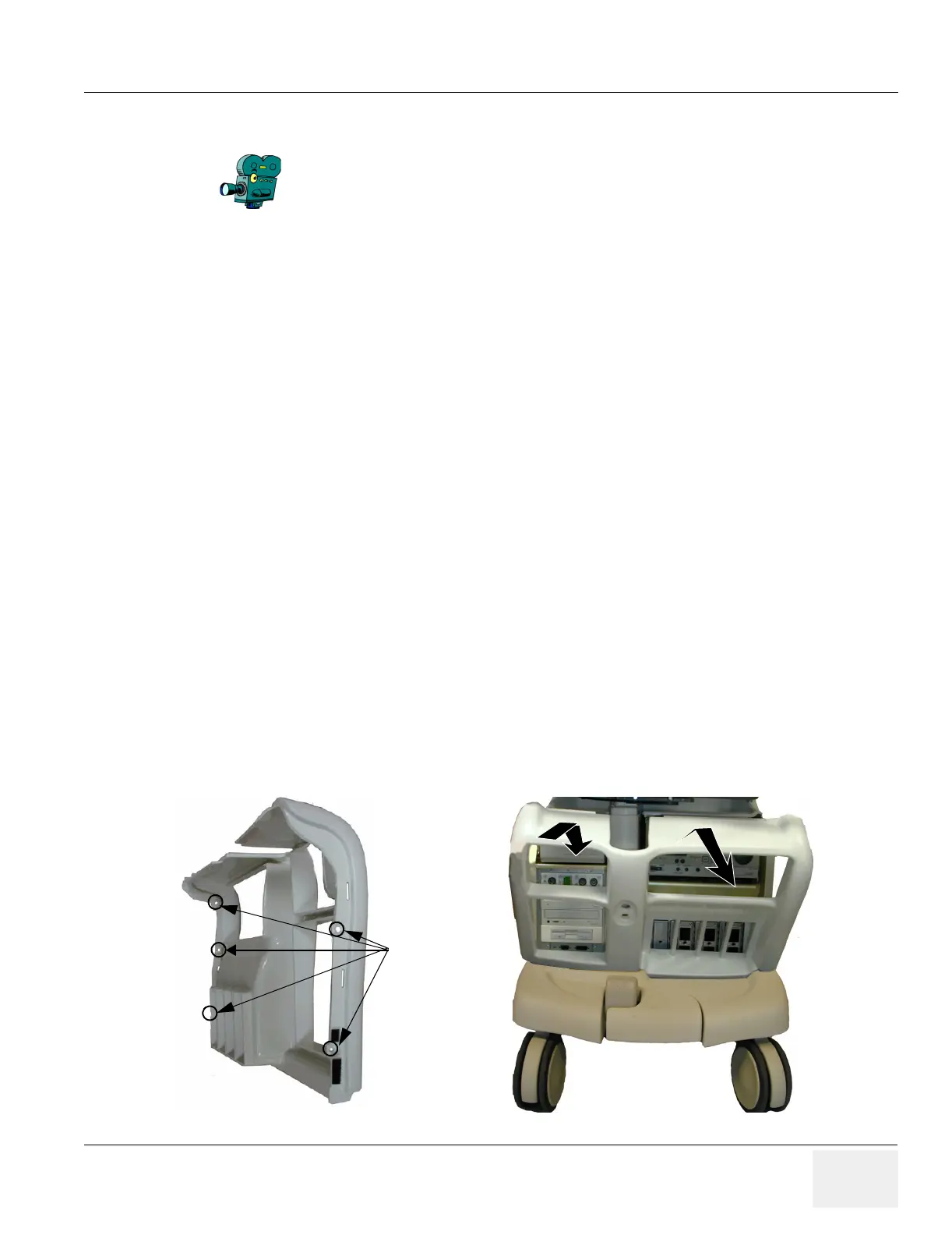
8-2-5-4 Removal procedure
1.) Unscrew the 5 Phillips screws that fasten the front cover to the chassis.
2.) Pull it outwards to free it from the top cover and the front Bumper as shown in Figure 8-5.
8-2-5-5 Installation Procedure
(click here to view the cover installation video)
1.) Position the front cover so it fits between the chassis and the bumper as shown Figure 8-5.
2.) Position the front cover so it links together with the top cover. You may have to loosen the two
Phillips screws on the top cover that are closest to the front cover.
3.) Fasten the front cover to the chassis with the five Phillips screws.
4.) Tighten the two Phillips screws in the top cover if they were loosened.
5.) Install the left- and right-side covers as described in Section 8-2-2 on page 8-5.
Select the movie camera icon to view the video of the Cover
removal procedure.
Figure 8-5 Removal/Installation of Front Cover
Screws (5)