GE MEDICAL SYSTEMS PROPRIETARY TO GE
D
IRECTION 2294854-100, REVISION 3 LOGIQ™ 9 PROPRIETARY MANUAL
8-8 Section 8-2 - Plastic Covers and Bumpers
8-2-4 Top Cover Replacement Procedure
8-2-4-1 Manpower
One person, 30 minutes
8-2-4-2 Tools
Phillips Screwdriver
8-2-4-3 Preparations
1.) Power Down/Shutdown the system as described in Section 4-3-2 on page 4-3
2.) Remove both left- and right-side covers as described in Section 8-2-2-4 on page 8-5.
3.) Remove upper rear cover as described in Section 8-2-3 on page 8-7.
8-2-4-4 Removal Procedure
1.) Move the Operarttor I/O up and forwards to its end positions.
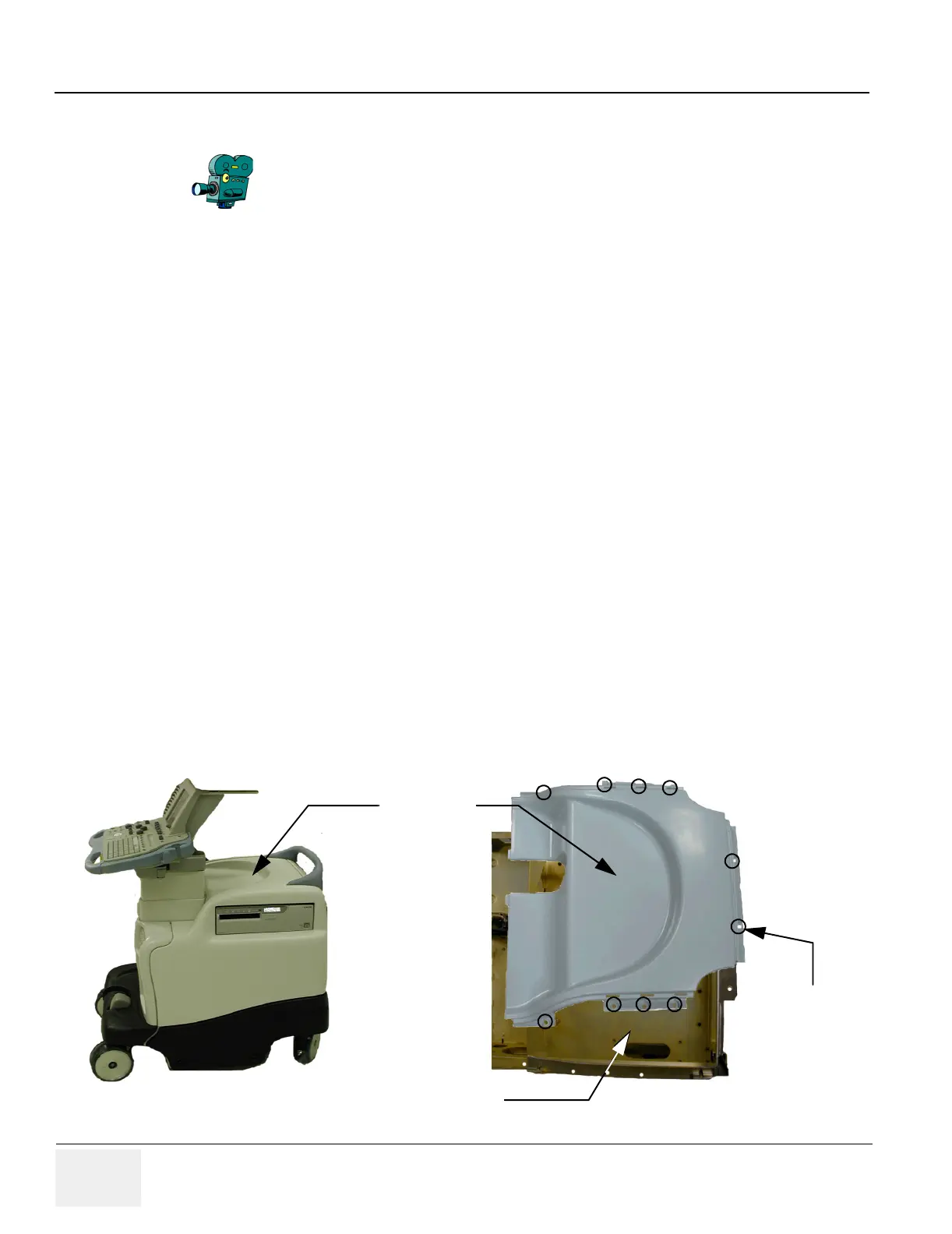
2.) Unscrew the 10 screws shown in Figure 8-4onpage8-8 .
3.) Pull the cover gently backwards and upwards to free the cover from the hoist area and allow it to
pass freely past the rear handle.
4.) Lift the top cover away from the scanner chassis.
8-2-4-5 Installation procedure
(click here to view the cover installation video)
1.) Position the top cover in place and fasten it with the 10 screws.
2.) Mount the side (Section 8-2-2 on page 8-5) and upper rear (Section 8-2-3 on page 8-7) covers.
3.) If required, Power On/Boot-up the system as described in Section 4-3-1 on page 4-2
Select the movie camera icon to view the video of the Cover
removal procedure.
Figure 8-4 Top Cover
Top Cover
Screws (10)
Chassis Shelf is
Printer Positioning Shelf