GE MEDICAL SYSTEMS PROPRIETARY TO GE
D
IRECTION 2294854-100, REVISION 3 LOGIQ™ 9 PROPRIETARY MANUAL
8-156 Section 8-38 - Brake/Direction Lock Assembly Replacement Procedure
Section 8-38
Brake/Direction Lock Assembly Replacement Procedure
8-38-1 Manpower
One person, 1 hour.
8-38-2 Tools
- Phillips screwdriver size 2
- Hexagon key 5 mm
- Torx screwdriver T-20
- Wrench 11 and 13 mm
8-38-3 Preparations (click here to view the cover removal video)
1.) Remove Front Bumper.
2.) Remove footrests on both pedals by unscrewing 4 Torx screws on each.
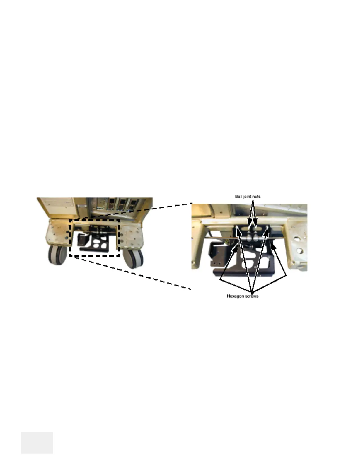
Figure 8-164 Brake Assembly