GE MEDICAL SYSTEMS PROPRIETARY TO GE
D
IRECTION 2294854-100, REVISION 3 LOGIQ™ 9 PROPRIETARY MANUAL
Chapter 5 Components and Functions (Theory) 5-33
5-5-1-2 Main Cable Connectors with Pinouts
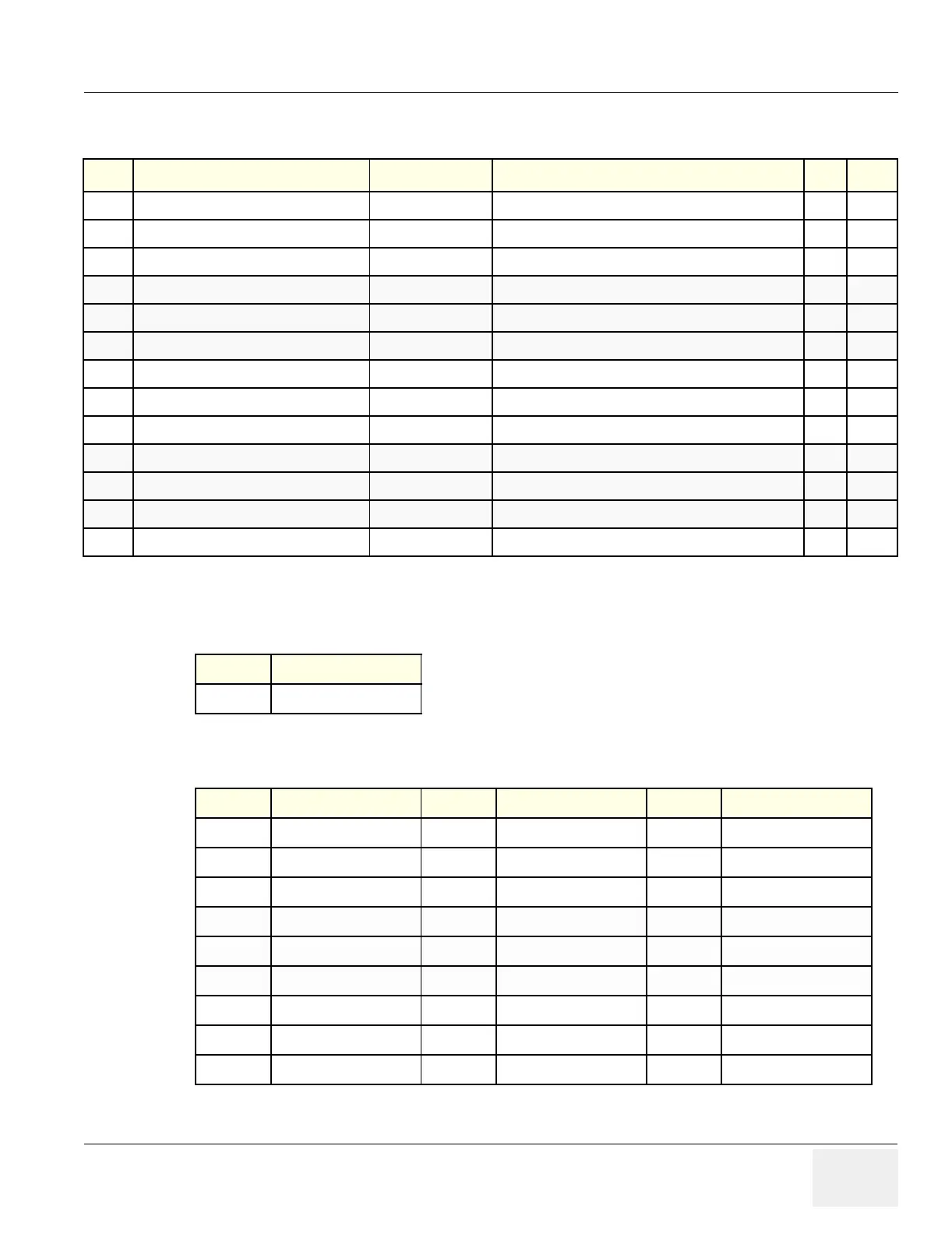
Table 5-11 Main Cable Composition
Item Function Lower to Description
A Safety Ground Connector A - G Safety Ground Connector
B DVI to DVI Interface B - I Interface to the Touch Screen B- I
C RGB to the Main Monitor C - H RGB to the Main Monitor C - H
D 110 VAC to the Main Monitor D - J 110 VAC to the Main Monitor D - J
E USB Audio, Microphone E - K USB Audio, Microphone and DC for Operator Panel
F DC Power and Control F - K DC Power and Control to the Operator panel
G Safety Ground Connector A - G Safety Ground Connector
H RGB to the Main Monitor C- H RGB to the Main Monitor C - H
I DVI to DVI Interface B - I Interface to the Touch Screen B - I
J 110 VAC to the Main Monitor D - J 110 VAC to the Main Monitor D - J
K USB Audio, Microphone and DC E/F - K USB Audio, Microphone and DC for Operator Panel
L Microphone to the Operator panel E - L to the Operator panel Microphone
M “Z” Release Cable From piston to “Z” relaese handle on the console
Table 5-12 Connector A & G- Safety Ground
Pin Signal
1 Ground
Table 5-13 Connector B & I - Touch Screen Interface
Pin Signal Pin Signal Pin Signal
1 LVDS Data 2- 10 LVDS Data 1+ 19 Ground
2 LVDS Data 2+ 11 Ground 20
3 Ground 12 21
4 13 22 Ground
5 14 +5V 23 LVDS Clock -
6 +5V 15 Return 24 LVDS Clock +
7 Return 16 +12V Backlight
8 17 LVDS Data 2-
9 LVDS Data 1- 18 LVDS Data 2-
 Loading...


