GE MEDICAL SYSTEMS PROPRIETARY TO GE
D
IRECTION 2294854-100, REVISION 3 LOGIQ™ 9 PROPRIETARY MANUAL
5-34 Section 5-5 - Operator Console Control PWA
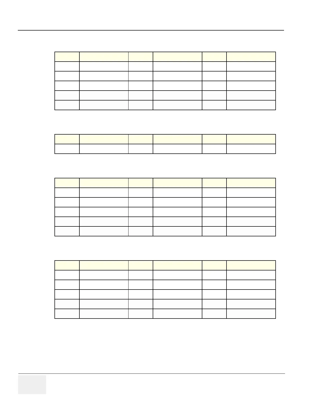
Table 5-14 Connector C & H - Touch Screen Interface
Pin Signal Pin Signal Pin Signal
1 Red 6 Red Ground 11 nc
2 Green 7 Green Ground 12 nc
3 Blue 8 Blue Ground 13 H Sync
4 nc 9 nc 14 V Sync
5 nc 10 Sync Ground 15 nc
Table 5-15 Connector D & J - 110VAC to Monitor
Pin Signal Pin Signal Pin Signal
1 110 VAC 2 Ground 3 Neutral
Table 5-16 Connector E - USB, Audio & Microphone
Pin Signal Pin Signal Pin Signal
1 nc 6 USB 5V 11 Ground Audio - Right
2 nc 7 USB 5V 12 Ground Microphone
3 Audio - Left 8 USB D+ 13 Ground USB
4 Audio - Right 9 nc 14 Ground USB
5 Microphone 10 Ground Audio - Left 15 USB D-
Table 5-17 Connector F - Op Console Power
Pin Signal Pin Signal Pin Signal
1 +15 6 +12V 11 Standby LED 0
2 +15 7 +12V 12 nc
3 nc 8 +12v 13 +12 Ground
4 On/Off SW0 9 +15 Ground 14 Ground USB
5 On/Off SW1 10 +15 Ground 15 USB D-
 Loading...


